
 Español
 中文简体
A diaphragm accumulator is a mechanical device that stores and releases energy using Boyle's Law (the compressibility of gases). Its core structure is a diaphragm made of a flexible material (usually ...
See Details
Home / News / Industry News / High Pressure Hydraulic Diaphragm Accumulator: Selection, Sizing and Supply Guide
High Pressure Hydraulic Diaphragm Accumulator: Selection, Sizing and Supply Guide
Admin 2026-10-23Content
A 315 bar clamping circuit on a die-casting machine has to hold force for about two seconds after the pump stops. A one litre diaphragm accumulator covers that duty with a precharge that stays within a few percent of its set value for months. The same job on a four litre bladder unit costs more, takes up three times the space and needs topping up more often.
That is the short answer. Above roughly 200 bar, with a small oil volume and a need for stable precharge between service intervals, a high pressure hydraulic diaphragm accumulator is usually the right choice. If you need more than two litres of usable oil from a single unit, or cost per litre matters more than response and gas retention, a bladder or piston design will serve you better. The rest of this article covers how the diaphragm design behaves under pressure, how to size and precharge it, and which details cause most field failures.
How a High Pressure Diaphragm Accumulator Works
A diaphragm accumulator is a pressure vessel divided into two chambers by a flexible diaphragm clamped between the shell halves. One side holds nitrogen precharge; the other connects to the circuit through the oil port. When circuit pressure rises above the precharge, oil enters and lifts the diaphragm, compressing the gas. When pressure falls, the gas expands and pushes the oil back out.
Two properties matter above 200 bar. The diaphragm is a light, clamped part with almost no moving mass, so it responds in milliseconds, which is useful for pressure spikes and pump pulsation. And because gas and oil never share a chamber, nitrogen cannot dissolve into the fluid and the fluid cannot foam into the gas side.
Bladder accumulators follow the same principle, but the bladder floats free inside the shell. At high pressure it can be extruded into the oil port, twisted in fast cycling duty or pinched against the wall. A clamped diaphragm cannot migrate, and the perforated disc behind the oil port supports it against extrusion. Because the diaphragm is fixed at its rim, the unit can also be mounted vertically, horizontally or at an angle, which often settles the question on skids and mobile equipment where there is no room for a bladder's vertical drop leg.
| Design | Typical maximum working pressure | Nominal volume range | Gas retention | Typical fit |
|---|---|---|---|---|
| Diaphragm | Up to 350 bar | 0.075 to 4 L | Very high; gas and oil separated by a clamped part | Compact high pressure circuits, pulsation damping, fast response |
| Bladder | Up to 350 bar | 0.5 to 60 L | Good, but the bladder can fail suddenly | General industrial energy storage at larger volumes |
| Piston | Up to 500 bar | 1 to 200 L | Lower; gas slowly passes the piston seals | Very large volumes and high flow rates |
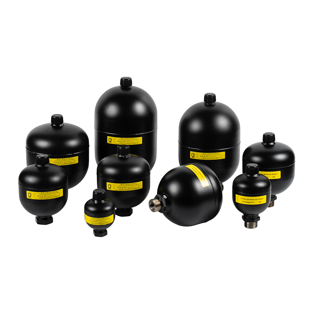 Welded Diaphragm Accumulators for Compact Hydraulic Energy StorageFixed-diaphragm hydraulic accumulators with steel shells, 0.075–3.5 L volumes and 210/250 bar ratings, suited to skids where vertical bladder mounting is impractical.View Product →
What a High Pressure Rating Actually Covers
Diaphragm accumulators are commonly offered at 200, 250 and 350 bar maximum working pressure. That figure is a rated maximum, not a test value: a 350 bar shell should be proof tested at 1.5 times rated pressure, and the design should be traceable to a pressure vessel code. In China that means a Special Equipment Manufacturing Licence for pressure vessels, with A2 covering high pressure vessels; exports to Europe require a PED assessment and CE marking.
- Support plate. The diaphragm needs a perforated support on the oil side so it cannot be pushed into the port at full discharge. Without it, the diaphragm fails by extrusion rather than fatigue.
- Diaphragm compound. NBR covers mineral oil at -20 to 80 degrees Celsius, HNBR extends that to about 120, FKM reaches 150 but suits only some fluids, and EPDM is usual for phosphate ester and glycol. The wrong compound can fail in weeks.
- Precharge drift with temperature. A unit charged to 180 bar at 20 degrees Celsius reads roughly 210 bar at 60. Sizing that ignores this shifts the working range and can lift a relief valve.
Ask for the material certificate and the pressure test record. A diaphragm accumulator is a pressure vessel, and the paperwork is part of the product.
Sizing and Precharge: The Numbers That Decide the Unit
Four inputs drive the selection:
- P2, the highest pressure the circuit will see, including surge.
- P1, the lowest pressure at which the accumulator must still deliver oil.
- Delta V, the oil volume needed for one discharge, whether that is a clamp-hold cycle, an hour of leakage compensation or the volume required to close a valve after the pump stops.
- Cycle time, which decides whether the nitrogen behaves isothermally or adiabatically.
Set precharge P0 between 0.8 and 0.9 times P1, and never above 0.9 times the rated maximum. The figure is always stated at 20 degrees Celsius.
Usable volume follows the standard polytropic relationship, with n at 1.0 for a slow, isothermal cycle and about 1.4 for a fast one. Take a 1 litre unit precharged to 180 bar in a circuit running between 200 and 350 bar. The isothermal calculation gives about 0.39 litres of usable oil; the adiabatic calculation gives roughly 0.14 litres. For a 0.5 litre discharge in two seconds, the first figure suggests a 1.5 litre unit and the second points to nearly 3.5 litres. Sizing on the isothermal result alone is one of the most common reasons a diaphragm accumulator appears not to hold pressure, when in fact it was simply too small.
Mounting, Piping and Accessories
Installation is straightforward, but three details separate a reliable job from a troublesome one.
- Use a safety block between the accumulator and the circuit. A combined ball valve with relief valve and bleed screw lets you isolate the unit, release trapped pressure and service the gas side safely. An AQF safety ball valve covers all three duties in one body.
- Never let the shell carry piping loads. Mount with brackets or hoops and use a hose where vibration is present; the vessel is a pressure boundary, not a structural member.
- Keep the connecting line short and generously sized. A long, narrow pipe adds pressure drop and slows the response, which defeats the purpose in pulsation damping.
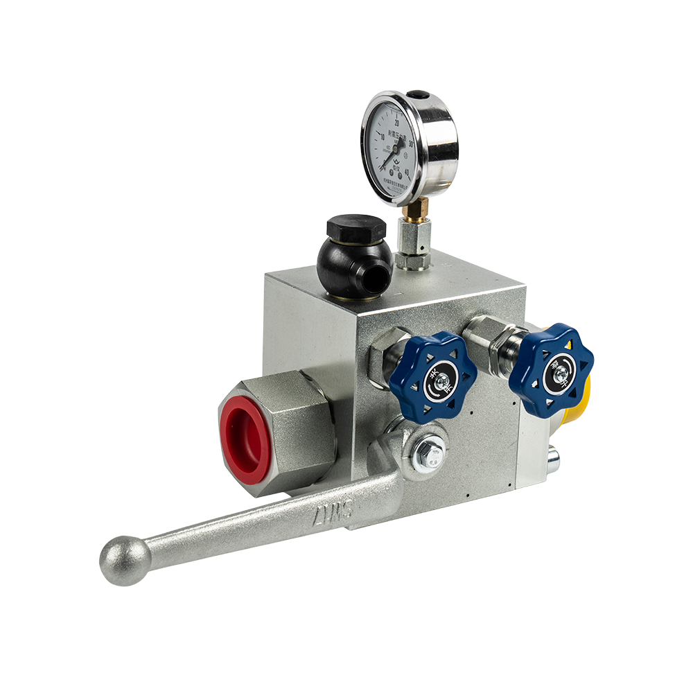 AQF Safety Ball Valves for Hydraulic Accumulator ProtectionAccumulator safety, shut-off and drain valves with straight, right-angle or three-way bodies, rated to 31.5 MPa and matched to common accumulator volumes.View Product →
Charging and Routine Maintenance
Charge with dry nitrogen of at least 99.99 percent purity. Never use oxygen, compressed air or any other gas; air brings in moisture, and oxygen plus oil under pressure is a fire risk inside the vessel.
Check the precharge with the circuit depressurised and the accumulator isolated, note the ambient temperature and correct the reading back to 20 degrees Celsius. A three-monthly check, or one every 500 operating hours, suits most industrial circuits. Diaphragm units lose very little gas when the charging valve is sound, so the valve core is the first suspect whenever pressure falls.
Stock two service parts: the charging valve core and the diaphragm. Replacing a diaphragm is a bench job with the right clamping fixture, and re-torquing the shell halves to the manufacturer's figure matters as much as the new part.
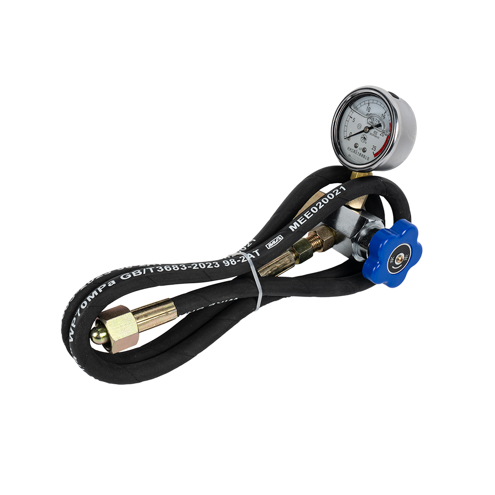 CQJ Nitrogen Charging Kits for Hydraulic AccumulatorsPortable charging and pressure-checking tools for accumulators, with gauges to 40 MPa, anti-backflow protection and optional hose lengths for confined spaces.View Product →
Procurement Checklist
Before ordering, confirm:
- Rated and proof pressure, both on the nameplate and in the test record.
- Pressure vessel documentation: manufacturing licence, PED or CE conformity, material certificates with heat numbers.
- Diaphragm compound matched to your fluid and temperature, not just the catalogue default.
- Effective volume rather than nominal volume, plus port size, thread standard and charging valve thread.
- Spare parts and cycle life data, with a factory delivery time rather than a distributor's shelf estimate.
Field Symptoms and Their Usual Causes
- Precharge falls within weeks but the unit still holds oil: the charging valve core is usually the cause, not the diaphragm.
- Pressure decays quickly after the pump stops: the diaphragm has ruptured or been extruded into the port.
- More oscillation than before on fast cycles: the precharge is low, or the unit was sized on an isothermal calculation and is undersized.
- Noise and water hammer: the accumulator sits too far from the valve, or the connecting line is too narrow.
FAQ
Can a diaphragm accumulator be precharged with air?
No. Air carries moisture that can freeze at the gas valve, and oxygen in contact with oil under pressure is a fire hazard. Dry nitrogen is the only correct medium.
How do I set precharge for a circuit running between 200 and 350 bar?
Between 0.8 and 0.9 times the minimum working pressure, so about 160 to 180 bar measured at 20 degrees Celsius. That keeps the diaphragm clear of the oil port at the low end while leaving usable volume at the high end.
Diaphragm or bladder?
The diaphragm is clamped at its rim and cannot migrate, which gives better gas retention, faster response and free mounting orientation. The bladder wins on volume per unit, from 0.5 litres upward, where diaphragm units stop at about 4 litres nominal.
A high pressure hydraulic diaphragm accumulator earns its place in a narrow but important set of duties: small volumes, high pressure, fast response and a precharge that stays where you set it. Getting it right comes down to four numbers, one precharge rule and an honest decision about whether the cycle is slow or fast.
We manufacture diaphragm accumulators alongside bladder and piston types in Xikou Town, Ningbo, with annual diaphragm capacity above 100,000 units, a Special Equipment Manufacturing Licence for pressure vessels (A2) and CE marking for export markets, from a workshop of more than 5,000 square metres. Sales run direct from the factory. Send your P1, P2, required oil volume and cycle time through the contact page and we will run the sizing with you.
PREV: Diaphragm Accumulator Nitrogen Charged: Precharge Pressure, Purity & Charging StepsNEXT: Diaphragm Accumulator for Wind Power Generator: Sizing, Precharge & Selection
Related Products
-
-
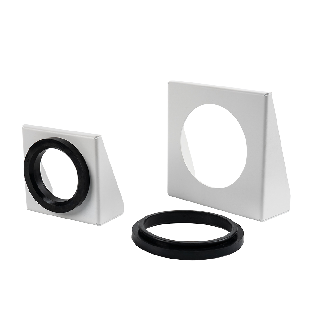
An accumulator bracket is a mechanical device used to fix and support a hydraulic accumulator.
See Details -
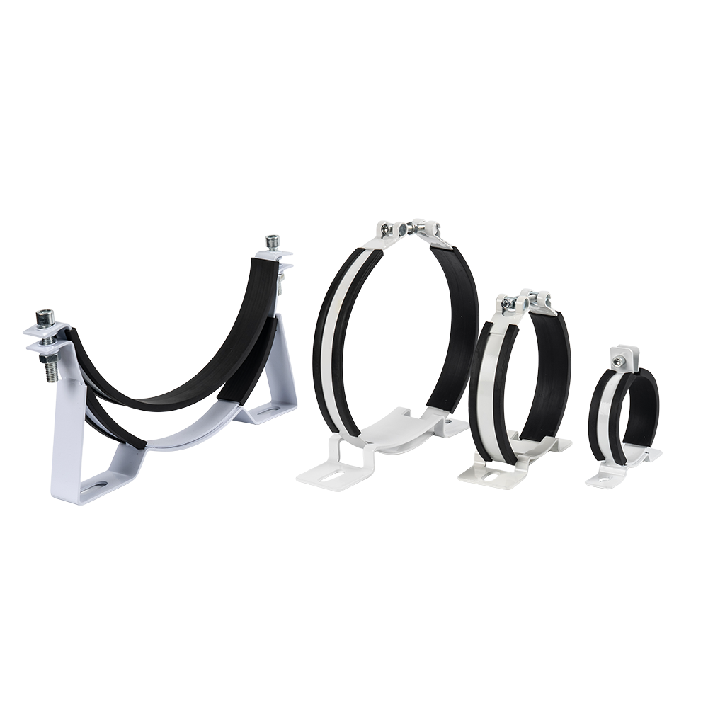
An accumulator clamp is a metal fastener specifically designed for securing and supporting hydraulic or pneumatic accumulators. Its primary function is to prevent the accumulator from swaying, deformi...
See Details -
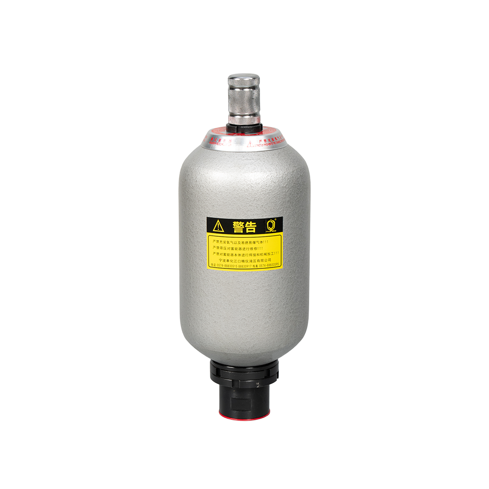
The NXQ Series Bladder Accumulator is a bladder-type accumulator conforming to national standards (JB/T 7036-93) or HG2331. Its core component is the "bladder" or "capsule," hence the name. This serie...
See Details -
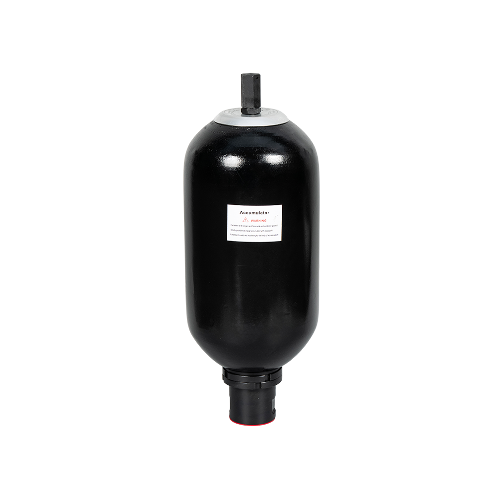
PED-type bladder accumulators refer to bladder accumulators that comply with the EU PED Directive (2014/68/EU). These accumulators typically consist of a steel outer shell and an internal elastic blad...
See Details -
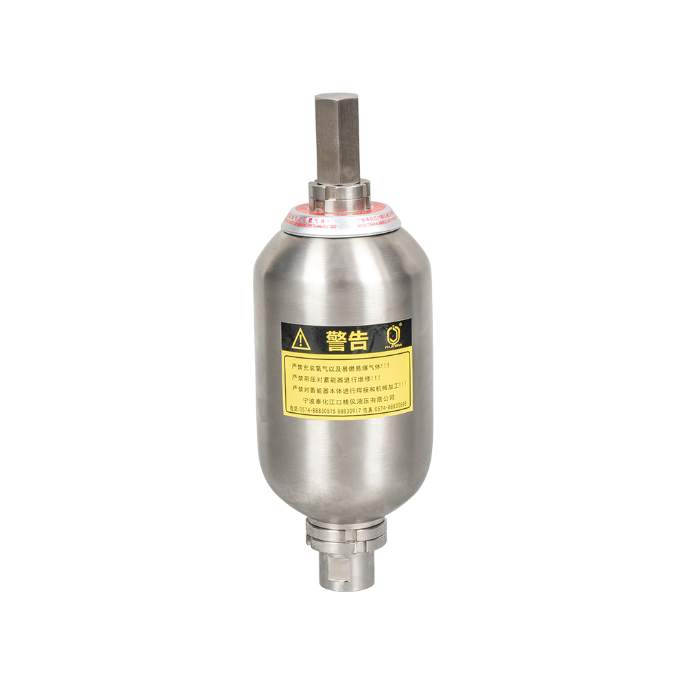
A stainless steel bladder accumulator is an energy storage device used in hydraulic systems. It utilizes the compressibility of a gas (usually nitrogen) to store and release energy, primarily for stab...
See Details
News
-
A 90 hp utility tractor working a front loader and a loaded grain trailer asks its hydraulic circuit to steer, lift and release the trailer brakes at the same time. When the small diaphragm accumulator support...
READ MORE -
A wellhead control panel on an offshore platform often carries less than two litres of usable hydraulic fluid behind each actuator. When the pump stops, that small volume still has to stroke a valve, hold it o...
READ MORE -
A hydraulic rock drill striking 2,500 times a minute pushes a pressure pulse into its circuit every 24 milliseconds. The hose flexes, the seals wear, and the pump sees the reflected wave. Diaphragm accumulator...
READ MORE -
A harvester header that sags a few centimetres every time pump load spikes, or a reel that surges as the engine drops to idle, points to the same root cause: pressure fluctuation that nothing in the circuit is...
READ MORE -
A 1.5 L threaded diaphragm accumulator screwed straight into a manifold block is one of the tidiest ways to hold clamping pressure on a machine tool. Charge it to 60 bar on a 20 °C bench, ship the same unit to...
READ MORE -
Picture a 3 MW turbine on a cold February night. The hydraulic power unit trips, the pump stops, and the pitch system has seconds to feather three blades. The only energy left is the nitrogen precharge sitting...
READ MORE
contact us

-

-

Mobile: +86-574-88830515
-

Telephone: +86-15968431761
-

No. 12 Xujiabu, Xikou Town, Fenghua District, Ningbo City, Zhejiang Province, P.R.China