
 Español
 中文简体
A diaphragm accumulator is a mechanical device that stores and releases energy using Boyle's Law (the compressibility of gases). Its core structure is a diaphragm made of a flexible material (usually ...
See Details
Home / News / Industry News / Diaphragm Accumulator for Offshore Oil Equipment: Selection & Supply Guide
Diaphragm Accumulator for Offshore Oil Equipment: Selection & Supply Guide
Admin 2026-10-02Content
A wellhead control panel on an offshore platform often carries less than two litres of usable hydraulic fluid behind each actuator. When the pump stops, that small volume still has to stroke a valve, hold it open against well pressure, and repeat the trick thousands of times across a field life. This is the duty diaphragm accumulators were built for, and the conclusion is worth stating up front: for low-volume, high-cycle, space-constrained circuits offshore, a diaphragm accumulator is usually the safer default over a bladder or piston unit.
The sections below explain why that is the case, which numbers actually drive the selection, and where offshore procurement teams tend to lose time and money.
Why Diaphragm Accumulators Fit Offshore Oil Equipment
In a diaphragm accumulator, gas and fluid are separated by a thin flexible diaphragm clamped or welded into the shell. There is no rolling bladder to chafe against the wall and no piston seal sliding along a honed bore. Fewer dynamic seals means fewer components that wear out between scheduled shutdowns, which matters when a service visit has to be booked around weather and crane availability.
- Fast response: fluid discharge begins almost immediately, which suits emergency shutdown pilots and quick-stroke valve actuators.
- Any mounting position: skids are crowded, and the design does not rely on gravity to keep gas and liquid in the right places.
- Compact, low-weight envelope: deck area and topside weight are budgeted items on every offshore project.
- Predictable gas retention: with no sliding gas-side seal, nitrogen loss is driven mainly by permeation through the diaphragm, so pre-charge checks stay repeatable.
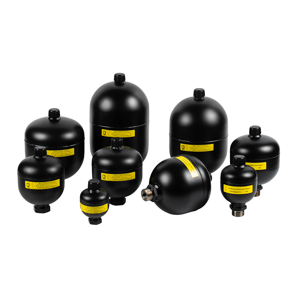 Diaphragm Accumulator for Compact Hydraulic Energy StorageUses a flexible diaphragm to separate gas and liquid, storing and releasing hydraulic energy with fewer dynamic seals for smaller, faster circuits and pilot-duty applications.View Product →
The trade-off is swept volume. Most diaphragm ranges stop in the low single digits of litres, so a circuit that must store tens of litres for a large actuator or a heave-compensation function still belongs to a bladder or piston unit. Diaphragm accumulators earn their place in the smaller, faster, more numerous circuits: wellhead control panels, shutdown valve pilots, choke and wing-valve actuators, BOP pilot lines, small winch and crane circuits, and the yard test benches that prove them. Related duty areas are listed on our marine and offshore hydraulic systems page.
As a rough screen, if the fluid volume needed per cycle is under about two litres and the cycle frequency is high, the diaphragm type is normally the first candidate worth quoting.
Diaphragm, Bladder or Piston: What Actually Changes Offshore
The three designs are not interchangeable, and the differences show up most clearly in small, fast circuits.
| Characteristic | Diaphragm | Bladder | Piston |
|---|---|---|---|
| Usable volume band | Smallest, low single-digit litres | Medium to large | Large and above |
| Response speed | Fastest | Fast | Slower, seal friction |
| Mounting orientation | Any position | Best vertical at low pressure | Orientation-sensitive |
| Gas-side dynamic seals | None | Gas valve interface | Piston seal plus gas valve |
| Cycle life at small swept volume | Very high | High | Moderate |
| Contamination sensitivity | Moderate | Moderate | High |
| Typical offshore duty | Panels, pilots, small actuators | Energy storage, pulsation damping | High-pressure bulk storage |
Specifying a Diaphragm Accumulator for Offshore Service
Pre-charge and working pressure
Pre-charge pressure is the most common source of field complaints. For energy storage, pre-charge is normally set between roughly 0.8 and 0.9 times the minimum working pressure of the circuit. For pulsation damping, values closer to 0.6 times the mean pressure are common. Set it too high and the accumulator cannot accept fluid at all; set it too low and the diaphragm flexes further than it was designed to.
Nameplate volume is not usable volume. During a rapid discharge, nitrogen behaves close to adiabatically (exponent near 1.4); a slow discharge is closer to isothermal (exponent of 1). Sizing with the wrong exponent quietly leaves you short of the fluid volume you assumed.
Temperature and elastomer choice
Offshore ambient can swing from about −20 °C on a winter deck to more than 50 °C in a hot climate, and hydraulic power unit oil commonly runs at 60 to 70 °C. Nitrile covers roughly −20 °C to +80 °C and remains the usual default. Fluoroelastomer extends the upper limit to around +120 °C at a small cost in low-temperature flexibility, while EPDM is the choice for phosphate ester and water-glycol fluids.
Fluid, cleanliness and documentation
Oilfield fluids add two complications: hydrogen sulphide and carbon dioxide drive corrosion on the wetted side, and fine particulate lodges between diaphragm and shell. A corrosion-resistant shell and a circuit held to an ISO 4406 target of 18/16/13 or better are common offshore specifications. For tighter, lower-volume systems, our note on diaphragm accumulators for small precision hydraulic systems goes further.
- Wellhead control panels
- BOP and choke pilots
- Hydraulic power units
- Winch and crane circuits
Illustrative split of typical offshore duty areas, not survey data.
Certification, Capacity and Procurement Risk
Offshore buyers rarely purchase on price alone. A diaphragm accumulator installed in a safety-related circuit usually has to arrive with a pressure equipment certification trail, and for European projects that means PED conformity and CE marking. In China the equivalent gate is the Special Equipment Manufacturing Licence for pressure vessels. Our own licence is issued at Grade A2 by the Zhejiang market regulator, and it is the document most often requested before a high-pressure unit is released into an export package.
- Material certificates for shell, diaphragm and gas valve
- Pressure test record for the shell
- Non-destructive examination report for gas-side welds
- Nameplate data matching the purchase order line by line
- Pre-charge record and the nitrogen purity used
- Declaration of conformity and CE marking where applicable
Capacity shapes schedule risk. A stated output of more than 100,000 diaphragm accumulators, 35,000 bladder units and 8,000 piston units per year absorbs a late design change far better than a workshop running to order.
Installation, Charging and Maintenance Offshore
Mounting details cause more failures than the accumulator itself. Use a purpose-made bracket or hoop rather than clamping the shell or hanging the unit from a pipe, keep the gas valve reachable from the walkway, and leave clearance for a charging hose.
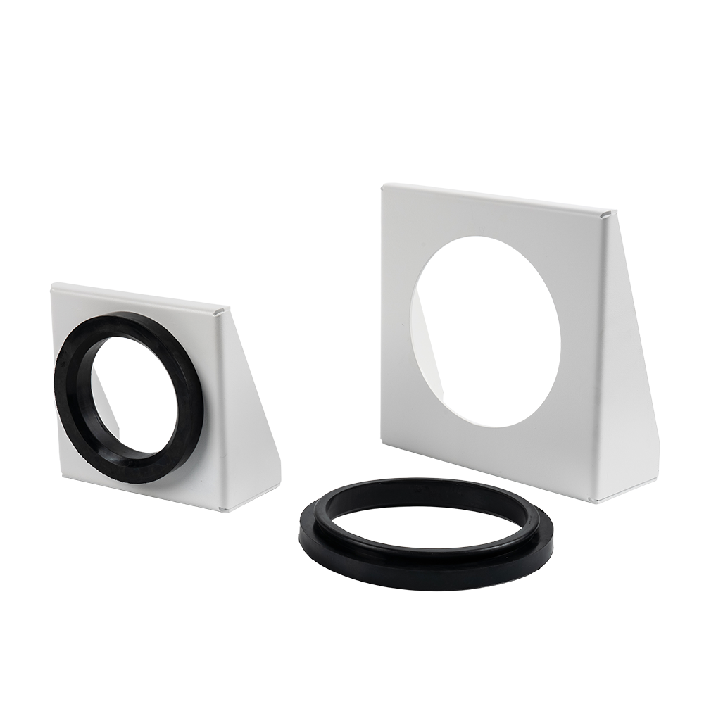 Accumulator Mounting Bracket and Clamp SupportProvides stable support for hydraulic accumulators, helping prevent displacement from vibration or pressure changes while keeping the gas valve accessible for charging and maintenance.View Product →
Charging is a controlled activity. Dry nitrogen at 99.9 percent purity or better is standard, and pre-charge should be set with the fluid side vented to atmosphere, then recorded on the tag and in the maintenance system. A dedicated charging kit reduces the risk of over-pressure or contamination.
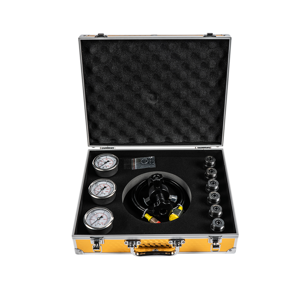 FPU Nitrogen Charging Kit for Hydraulic AccumulatorsMulti-functional kit for charging, replenishing, and adjusting accumulator pre-charge pressure, with adapters for bladder, piston, diaphragm, and bellows types; supports controlled maintenance.View Product →
- Check pre-charge pressure 6 to 12 months after commissioning, then annually.
- Inspect shell and bracket for corrosion, especially at welds and coating damage.
- Replace the diaphragm when pre-charge cannot be held or the gas valve leaks.
- Log every top-up so nitrogen loss trends become visible.
Frequently Asked Questions
What pre-charge should I specify for an offshore panel?
Start at 0.8 to 0.9 times the minimum working pressure for energy storage, then confirm usable volume against the discharge rate. For pulsation damping, 0.6 times the mean pressure is a common starting point.
Can a diaphragm accumulator be mounted horizontally?
Yes. The design does not rely on the gas pocket sitting at the top, so orientation is mainly a plumbing and access question rather than a performance one.
How do I know the diaphragm has failed?
The usual signs are a pre-charge that will not hold, a sudden drop in usable volume, or nitrogen detected at the fluid-side connection. Failure is rarely dramatic, which is exactly why pre-charge logs matter.
Diaphragm accumulators are not the answer to every offshore hydraulic problem, but for the small, fast, repetitive circuits that keep a platform safe they are usually the cleanest answer. The selection itself is rarely complicated: match swept volume to duty, set pre-charge against minimum working pressure, choose the elastomer against real temperature and fluid, and insist on the certification trail before the unit ships.
If you are specifying for a wellhead panel, a BOP pilot skid or a compact power unit, send us your duty figures and we will return a sized recommendation with the documentation package attached.
PREV: Diaphragm Accumulator for Tractor Hydraulic Systems: Sizing & Buying GuideNEXT: Diaphragm Accumulator for Mining Machinery: Selection, Sizing and Maintenance
Related Products
-
-

An accumulator bracket is a mechanical device used to fix and support a hydraulic accumulator.
See Details -
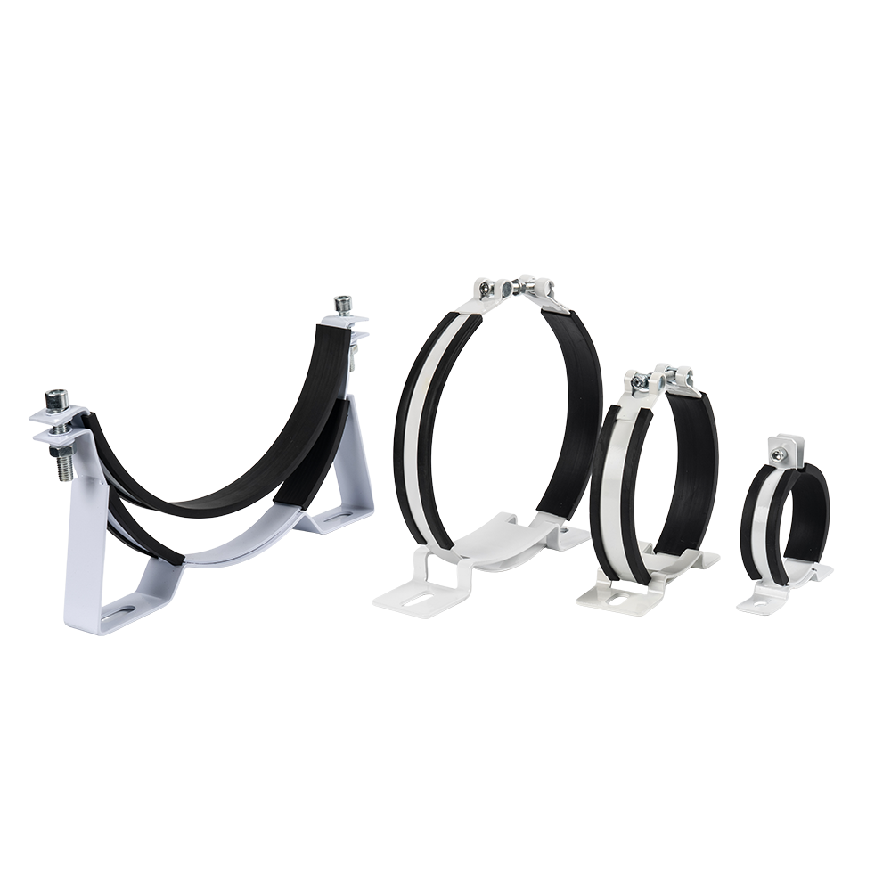
An accumulator clamp is a metal fastener specifically designed for securing and supporting hydraulic or pneumatic accumulators. Its primary function is to prevent the accumulator from swaying, deformi...
See Details -
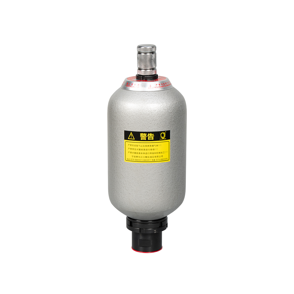
The NXQ Series Bladder Accumulator is a bladder-type accumulator conforming to national standards (JB/T 7036-93) or HG2331. Its core component is the "bladder" or "capsule," hence the name. This serie...
See Details -
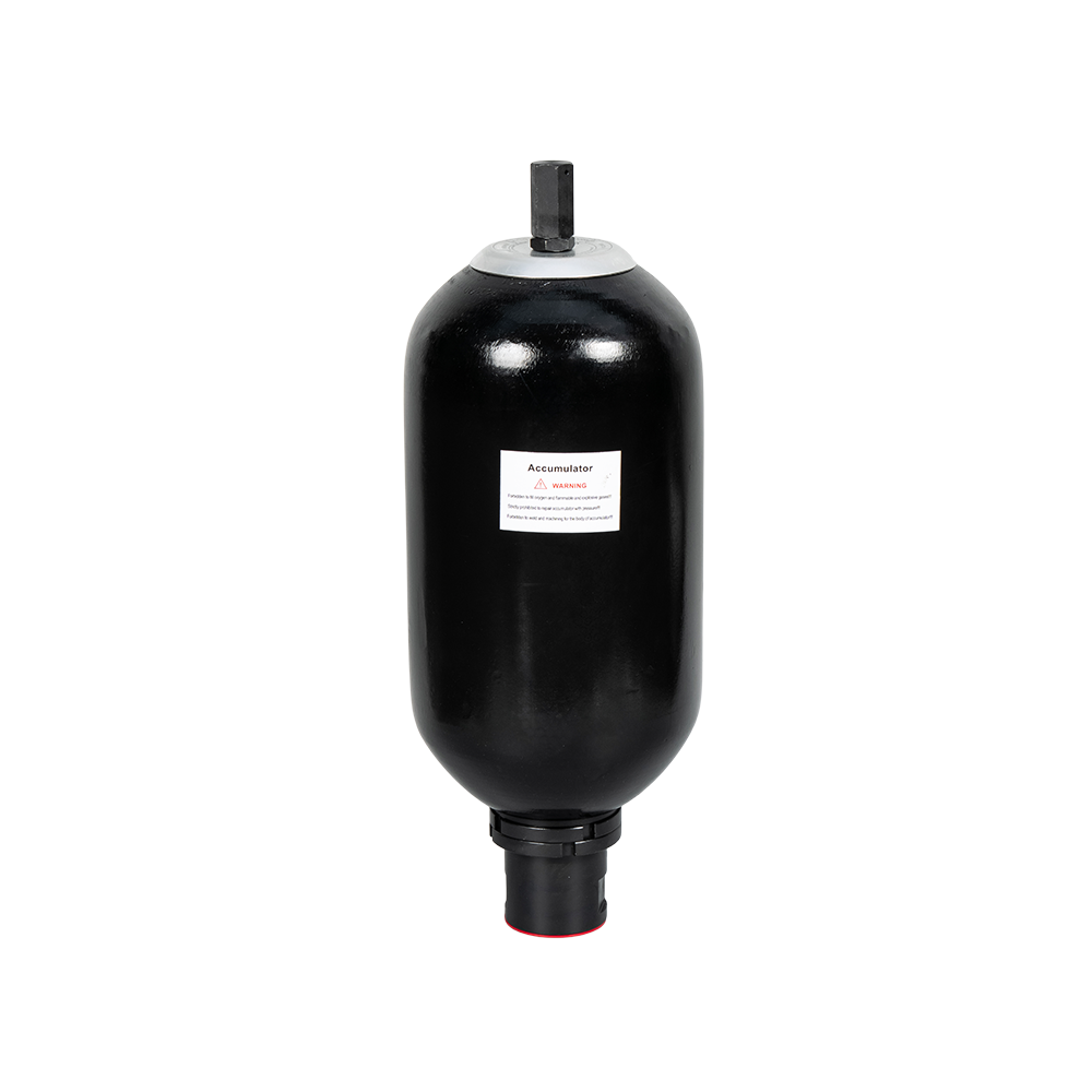
PED-type bladder accumulators refer to bladder accumulators that comply with the EU PED Directive (2014/68/EU). These accumulators typically consist of a steel outer shell and an internal elastic blad...
See Details -
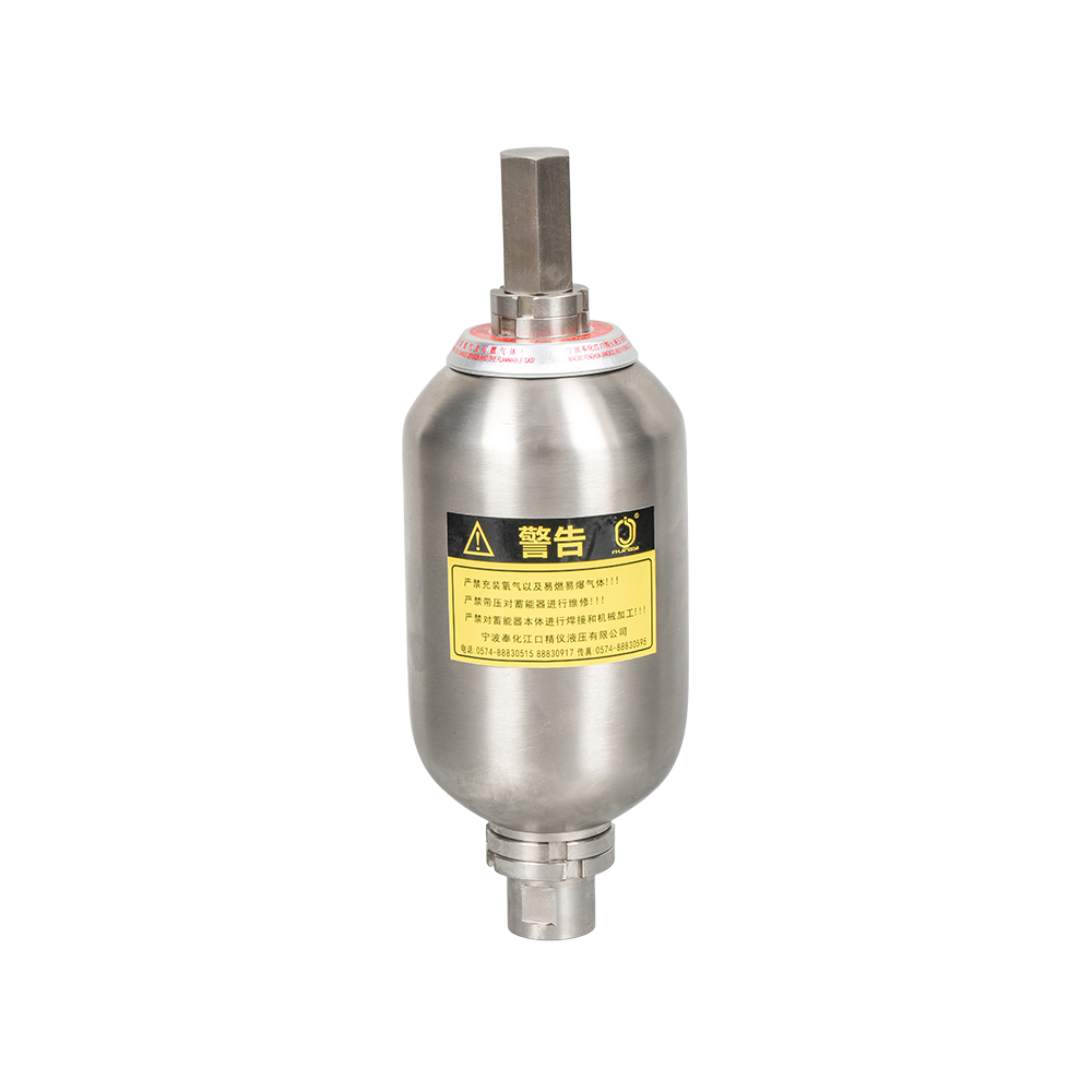
A stainless steel bladder accumulator is an energy storage device used in hydraulic systems. It utilizes the compressibility of a gas (usually nitrogen) to store and release energy, primarily for stab...
See Details
News
-
During a typical injection molding cycle, the hydraulic system demands a sudden surge of oil to drive the injection screw forward at high speed. If the pump alone supplies this flow, it must be oversized, wast...
READ MORE -
A 315 bar clamping circuit on a die-casting machine has to hold force for about two seconds after the pump stops. A one litre diaphragm accumulator covers that duty with a precharge that stays within a few per...
READ MORE -
Picture a 3 MW turbine on a cold February night. The hydraulic power unit trips, the pump stops, and the pitch system has seconds to feather three blades. The only energy left is the nitrogen precharge sitting...
READ MORE -
A 90 hp utility tractor working a front loader and a loaded grain trailer asks its hydraulic circuit to steer, lift and release the trailer brakes at the same time. When the small diaphragm accumulator support...
READ MORE -
A hydraulic rock drill striking 2,500 times a minute pushes a pressure pulse into its circuit every 24 milliseconds. The hose flexes, the seals wear, and the pump sees the reflected wave. Diaphragm accumulator...
READ MORE -
A harvester header that sags a few centimetres every time pump load spikes, or a reel that surges as the engine drops to idle, points to the same root cause: pressure fluctuation that nothing in the circuit is...
READ MORE
contact us

-

-

Mobile: +86-574-88830515
-

Telephone: +86-15968431761
-

No. 12 Xujiabu, Xikou Town, Fenghua District, Ningbo City, Zhejiang Province, P.R.China