 English
 Español
 中文简体
中文简体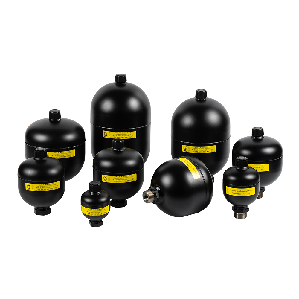
Model Designations
1. Series Code:
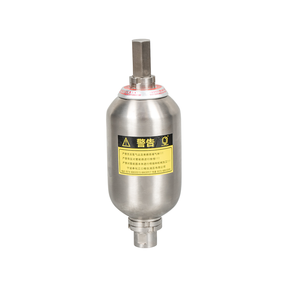
Welded diaphragm accumulators
2. Construction:
A: (M28X1.5) Rechargeable
B: Completely sealed¹
3. Nominal Volume(L)
4. Allowable working pressure(Bar)
5. Shell Material:
1--Carbon steel
6. Diaphragm Material code:
1--Nitrile Butadiene Rubber (NBR)
2--Hydrogenated Nitrile Butadiene Rubber (HNBR)²
3--Isobutylene Isoprene Rubber (IIR)²
7--Epichlorohydrin Rubber (ECO)²
7. Liquid side standard connection AK or AB³
8. Nitrogen pre-charge pressure at 20°C (Bar)¹
Note:
(1) Only for bulk orders of Type A and Type B;
(2) Only for bulk orders;
(3) For non-standard connectors, please consult separately.
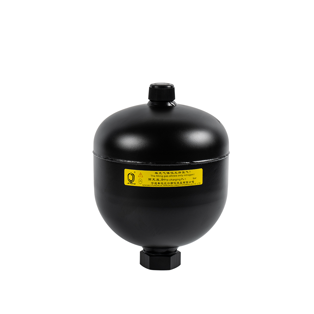
Welded Diaphragm accumulator use steel stamping shell, They have two types according to the gas side: Rechargeable and completely sealed.
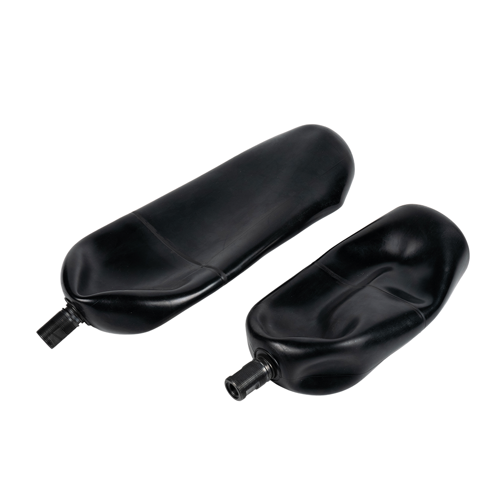
Diaphragm Accumulator
A diaphragm accumulator is a mechanical device that stores and releases energy using Boyle's Law (the compressibility of gases). Its core structure is a diaphragm made of a flexible material (usually rubber) that completely separates the liquid chamber from the gas chamber inside the container.
Core Working Principle
The operation of a diaphragm accumulator is based on the volume change relationship between gas and liquid:
1. Energy Storage (Charging): When the pressure in the hydraulic system increases, liquid is forced into the liquid chamber of the accumulator.
The entry of liquid forces the flexible diaphragm to move towards the gas chamber, compressing the gas (usually nitrogen) on the other side of the diaphragm.
Due to the gas compression, potential energy (compression energy) is stored.
2. Energy Release (Release): When the system pressure decreases (e.g., when a hydraulic cylinder needs to move rapidly), the diaphragm is pushed back to its original shape by the internal pressure of the gas.
The elasticity of the diaphragm expands the compressed gas, pushing the liquid back into the hydraulic system to replenish the instantaneous flow demand.
Functions of Hydraulic Accumulators
An indispensable component in hydraulic and fluid technology. It has many uses in hydraulic circuits, such as:
1) saving drive power;
2) energy storage;
3) damping pressure shocks;
4) reducing pump pressure pulsation;
5) maintaining constant pressure.
All of these functions can be performed by hydraulic accumulators, thus yielding special benefits such as: increased productivity and overall efficiency, improved functionality, extended lifespan, enhanced safety, and reduced operating and maintenance costs.
Product
Description
We can design and develop according to the needs of our customers to meet the requirements of different clients.
Product Specifications
Model Code and Size
| Nominal Volume (L) | Compression Ratio p₂:p₀ | Series | Allowable Working Pressure (bar) | L (mm) | ΦD (mm) | Weight (kg) | Displacement | Standard fluid connection | |||||||||
| AK | AB | ||||||||||||||||
| M1 (ISO228) | ΦG (mm) | L1 (mm) | B1 (mm) | Hex SW | M2 (ISO228) | M3 | L2 (mm) | B2 (mm) | Hex SW | ||||||||
| 0.075 | 8:01 | 210 | 210 | 91 | 65 | 0.7 | 38/95/150 | G1/2 | Φ29 | 16 | 18 | 32 | Not provided | - | - | - | - |
| 0.075 | 8:01 | 250 | 250 | 91 | 65 | 0.7 | 38/95/150 | G1/2 | Φ29 | 16 | 18 | 32 | Not provided | - | - | - | - |
| 0.16 | 8:01 | 210 | 210 | 96 | 75 | 0.9 | 38/95/150 | G1/2 | Φ29 | 16 | 18 | 32 | Not provided | - | - | - | - |
| 0.16 | 8:01 | 250 | 250 | 96 | 75 | 0.9 | 38/95/150 | G1/2 | Φ29 | 16 | 18 | 32 | Not provided | - | - | - | - |
| 0.25 | 8:01 | 100 | 100 | 106 | 80 | 0.8 | 38/95/150 | G1/2 | Φ29 | 16 | 18 | 32 | Not provided | - | - | - | - |
| 0.25 | 8:01 | 210 | 210 | 112 | 86.5 | 1.45 | 38/95/150 | G1/2 | Φ29 | 16 | 18 | 32 | Not provided | - | - | - | - |
| 0.25 | 8:01 | 250 | 250 | 112 | 86.5 | 1.45 | 38/95/150 | G1/2 | Φ29 | 16 | 18 | 32 | Not provided | - | - | - | - |
| 0.32 | 8:01 | 100 | 100 | 116.5 | 89 | 1.1 | 38/95/150 | G1/2 | Φ29 | 16 | 18 | 32 | Not provided | - | - | - | - |
| 0.32 | 8:01 | 210 | 210 | 121 | 95 | 1.75 | 38/95/150 | G1/2 | Φ29 | 16 | 18 | 32 | Not provided | - | - | - | - |
| 0.32 | 8:01 | 250 | 250 | 121 | 95 | 1.75 | 38/95/150 | G1/2 | Φ29 | 16 | 18 | 32 | Not provided | - | - | - | - |
| 0.35 | 8:01 | 100 | 100 | 121 | 89 | 1.15 | 38/95/150 | G1/2 | Φ29 | 16 | 18 | 32 | Not provided | - | - | - | - |
| 0.35 | 8:01 | 210 | 210 | 124 | 95 | 1.8 | 38/95/150 | G1/2 | Φ29 | 16 | 18 | 32 | Not provided | - | - | - | - |
| 0.35 | 8:01 | 250 | 250 | 124 | 95 | 1.8 | 38/95/150 | G1/2 | Φ29 | 16 | 18 | 32 | Not provided | - | - | - | - |
| 0.5 | 8:01 | 210 | 210 | 133 | 106 | 2.3 | 38/95/150 | G1/2 | Φ34 | 18 | 22 | 41 | G1/2 | M33X1.5 | 18 | 38 | 41 |
| 0.5 | 8:01 | 250 | 250 | 133 | 106 | 2.3 | 38/95/150 | G1/2 | Φ34 | 18 | 22 | 41 | G1/2 | M33X1.5 | 18 | 38 | 41 |
| 0.75 | 8:01 | 210 | 210 | 148.5 | 121 | 3 | 38/95/150 | G1/2 | Φ34 | 18 | 22 | 41 | G1/2 | M33X1.5 | 18 | 38 | 41 |
| 0.75 | 8:01 | 250 | 250 | 152 | 123 | 3.5 | 38/95/150 | G1/2 | Φ34 | 18 | 22 | 41 | G1/2 | M33X1.5 | 18 | 38 | 41 |
| 1 | 8:01 | 210 | 210 | 160 | 138 | 3.8 | 38/95/150 | G1/2 | Φ34 | 18 | 22 | 41 | G1/2 | M33X1.5 | 18 | 38 | 41 |
| 1 | 8:01 | 250 | 250 | 163 | 142 | 5 | 38/95/150 | G1/2 | Φ34 | 18 | 22 | 41 | G1/2 | M33X1.5 | 18 | 38 | 41 |
| 1.4 | 8:01 | 210 | 210 | 174 | 153 | 5.9 | 38/95/150 | G1/2 | Φ34 | 18 | 22 | 41 | G1/2 | M33X1.5 | 18 | 38 | 41 |
| 1.4 | 8:01 | 250 | 250 | 174 | 153 | 5.9 | 38/95/150 | G1/2 | Φ34 | 18 | 22 | 41 | G1/2 | M33X1.5 | 18 | 38 | 41 |
| 2 | 8:01 | 210 | 210 | 202 | 169 | 7.6 | 38/95/150 | G1/2 | Φ34 | 18 | 22 | 41 | G1/2 | M33X1.5 | 18 | 38 | 41 |
| 2 | 8:01 | 250 | 250 | 205 | 172 | 9.2 | 38/95/150 | G1/2 | Φ34 | 18 | 22 | 41 | G1/2 | M33X1.5 | 18 | 38 | 41 |
| 2.8 | 4:01 | 210 | 210 | 250 | 169 | 9.2 | 38/95/150 | G3/4 | Φ42 | 24 | 28 | 46 | G3/4 | M45X1.5 | 20 | 37 | 46 |
| 2.8 | 4:01 | 250 | 250 | 255 | 172 | 11.5 | 38/95/150 | G3/4 | Φ42 | 24 | 28 | 46 | G3/4 | M45X1.5 | 20 | 37 | 46 |
| 3.5 | 4:01 | 210 | 210 | 289 | 173 | 13.8 | 38/95/150 | G3/4 | Φ42 | 24 | 28 | 46 | G3/4 | M45X1.5 | 20 | 37 | 46 |
| 3.5 | 4:01 | 250 | 250 | 289 | 173 | 13.8 | 38/95/150 | G3/4 | Φ42 | 24 | 28 | 46 | G3/4 | M45X1.5 | 20 | 37 | 46 |
-
The NXQ Series Bladder Accumulator is a bladder-type accumulator conforming to national standards (JB/T 7036-93) or HG2331. Its core component is the "bladder" or "capsule," hence the name. This serie...
See Details -
PED-type bladder accumulators refer to bladder accumulators that comply with the EU PED Directive (2014/68/EU). These accumulators typically consist of a steel outer shell and an internal elastic blad...
See Details -
A stainless steel bladder accumulator is an energy storage device used in hydraulic systems. It utilizes the compressibility of a gas (usually nitrogen) to store and release energy, primarily for stab...
See Details -
A diaphragm accumulator is a mechanical device that stores and releases energy using Boyle's Law (the compressibility of gases). Its core structure is a diaphragm made of a flexible material (usually ...
See Details -
A Piston Accumulator is a mechanical device that uses the compressibility of a gas (usually nitrogen) to store hydraulic energy. It is widely used in hydraulic systems as an energy regulator. It isola...
See Details -
JINGYI Hydraulic Corporation offers a series of full-bladder accumulator stations, which include a fixed bolster, bag-type accumulator, a control valve group, ball valve, pipeline, oil return pipe, et...
See Details -
The NXQ Series Accumulator Bladder is a critical energy storage element in hydraulic systems, primarily responsible for absorbing energy fluctuations and releasing energy to smooth system operation.
See Details -

PED-type accumulator bladders refer to the internal rubber bladders (sacs) of hydraulic accumulators that comply with the European Pressure Equipment Directive (PED). These bladder-type accumulators a...
See Details -
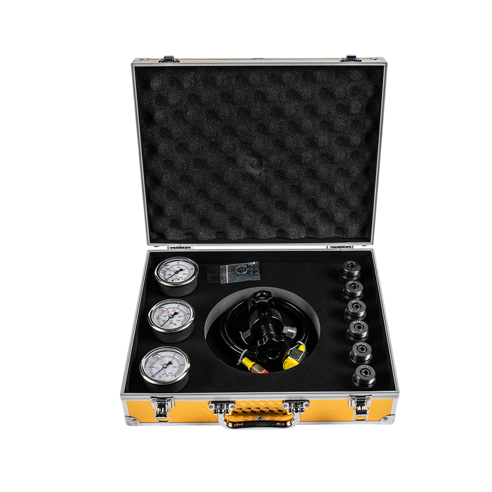
An FPU Charging Kit is a multi-functional tool kit specifically designed for the maintenance of hydraulic accumulators. Its core function is to charge, replenish, or adjust the pre-charge pressure of ...
See Details -
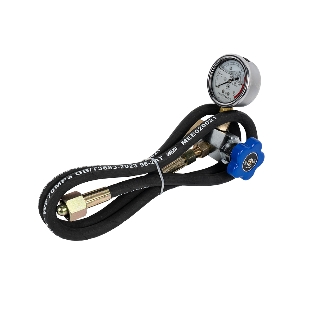
The CQJ charging kit is a specialized tool for charging, replenishing, correcting, and checking the charging pressure of accumulators in hydraulic systems.
See Details -
The 5/8 UNF Charging kit is a high-pressure tool specifically designed for charging or filling hydraulic systems (such as accumulators) with nitrogen or gas. "UNF" refers to the thread specification o...
See Details -
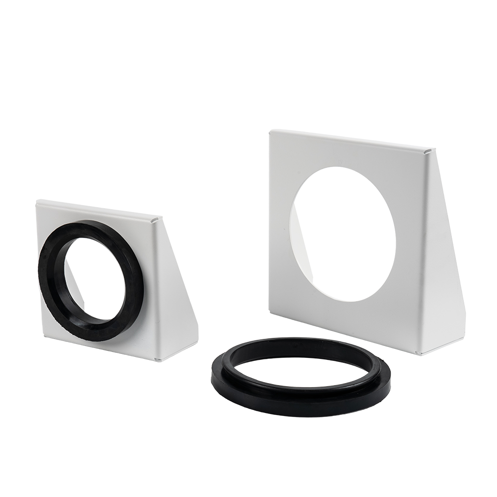
An accumulator bracket is a mechanical device used to fix and support a hydraulic accumulator.
See Details
contact us
-

-

Mobile: +86-574-88830515
-

Telephone: +86-15968431761
-

No. 12 Xujiabu, Xikou Town, Fenghua District, Ningbo City, Zhejiang Province, P.R.China