
 Español
 中文简体
A diaphragm accumulator is a mechanical device that stores and releases energy using Boyle's Law (the compressibility of gases). Its core structure is a diaphragm made of a flexible material (usually ...
See Details
Home / News / Industry News / Diaphragm Accumulator for Wind Power Generator: Sizing, Precharge & Selection
Diaphragm Accumulator for Wind Power Generator: Sizing, Precharge & Selection
Admin 2026-10-16Content
- 1 Why a Wind Turbine Needs Stored Energy
- 2 Why the Diaphragm Design Fits Wind Power Generators
- 3 Sizing and Precharge: The Numbers Behind a Safe Feather
- 4 Materials, Temperature and Certification
- 5 Common Procurement Mistakes
- 6 What to Look For in the Manufacturer
- 7 Frequently Asked Questions
- 8 Getting the Selection Right the First Time
Picture a 3 MW turbine on a cold February night. The hydraulic power unit trips, the pump stops, and the pitch system has seconds to feather three blades. The only energy left is the nitrogen precharge sitting behind a thin flexible separator inside an accumulator on the manifold. That separator is a diaphragm, and whether it releases its oil fast enough after months of standing still at minus 20 degrees decides whether the event becomes a maintenance ticket or an insurance claim.
For most wind power generator duties, a welded diaphragm accumulator is the right default: pitch emergency actuation, rotor and yaw brake circuits, and pulsation damping on the hydraulic power unit. The detail that decides success is rarely the catalogue volume. It is sizing, precharge and certification.
Why a Wind Turbine Needs Stored Energy
Turbine hydraulics do four jobs, and three of them depend on stored energy.
- Pitch actuation. Safety practice under IEC 61400-1 expects the blades to feather on power or hydraulic loss, and the accumulator supplies the emergency volume that drives the pitch cylinders to the safe position.
- Brakes. Rotor and yaw brakes are usually released hydraulically and applied by springs; the accumulator provides the release flow and damps the chatter.
- Pulsation damping. A piston pump sends pressure ripples through the circuit that fatigue seals and instruments, and a gas-charged unit mounted near the pump absorbs them.
- Leakage and thermal compensation. A closed circuit that swings from -30 °C at start-up to +70 °C in operation changes volume, and the accumulator absorbs it without lifting the relief valve.
Emergency pitch circuits on 2-6 MW turbines typically use 0.5-4 L units at 200-350 bar, while larger platforms with a shared ring main go to 10 L or use a small accumulator station.
Why the Diaphragm Design Fits Wind Power Generators
A diaphragm accumulator separates gas and oil with a formed metal diaphragm. There is no bladder neck to extrude, no piston seal to roll, and no route for nitrogen to migrate into the oil. In a nacelle, where a gas top-up costs a technician, a crane and a weather window, gas retention is worth far more than purchase price.
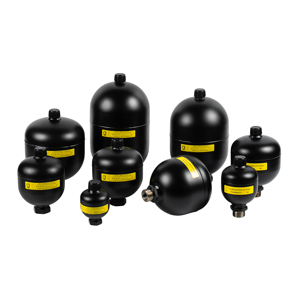 Diaphragm Accumulator for Hydraulic Energy StorageSeparates gas and oil with a flexible diaphragm; 0.075–3.5 L sizes and 38/95/150 bar pressures suit pitch systems needing gas retention.View Product →
Diaphragm, bladder and piston side by side
| Criterion | Diaphragm | Bladder | Piston |
|---|---|---|---|
| Gas retention | Very high, welded shell, no elastomer neck | Good, the bladder neck is the weak point | Good, seal rings allow slow loss |
| Response and flow | Fast, very low moving mass | Fast | Slower, moving mass and seal friction |
| Usable volume ratio | About 40-55% of nominal | About 50-70% of nominal | About 80-90% of nominal |
| Practical volume range | 0.075-4 L, larger on request | 0.5-60 L | 0.5-100 L |
| Maximum working pressure | 250-350 bar | 200-350 bar | 350 bar |
| Mounting orientation | Any position, gas side up preferred | Vertical, oil port down | Any position |
| Wear parts | Diaphragm only, no sliding contact | Bladder | Piston seals and cylinder bore |
| Typical wind use | Pitch emergency, brake circuits, damping | Large ring main when volume matters | High cycle, high flow, shaft brake |
For a pitch system that feathers twice a year, the diaphragm wins on gas retention and response time. A 20 L ring main cycling every few seconds still favours a piston design, and a bladder unit remains sensible when the volume is large and the mounting is vertical.
Sizing and Precharge: The Numbers Behind a Safe Feather
Catalogues quote nominal volume. The turbine gets usable volume, meaning the oil released between minimum working pressure and maximum system pressure. In a diaphragm unit that is roughly 40-55% of nominal, far less than most first-time buyers expect.
A worked example for a 2 MW pitch circuit:
- Minimum working pressure required by the pitch cylinder: p1 = 120 bar.
- Maximum system pressure: p2 = 250 bar.
- Precharge at 20 °C: p0 = 0.9 times p1 = 110 bar.
- Oil needed for one feather stroke: 0.35 L.
- Nominal volume: 0.35 / 0.45 = about 0.8 L, so specify a 1 L unit.
Two corrections are routinely forgotten. Nitrogen follows p/T, so 110 bar set at 20 °C becomes roughly 91 bar at -30 °C, and sizing must use the cold case rather than the workshop case. A feather stroke lasting under two seconds also behaves closer to adiabatic than isothermal, which cuts usable volume further. Precharge then has to be set and later verified with a proper charging kit: a regulated nitrogen source, a pressure-rated hose and a gauge accurate to within 1% of full scale. Setting it by feel with a workshop compressor leaves the accumulator either oil-logged or empty.
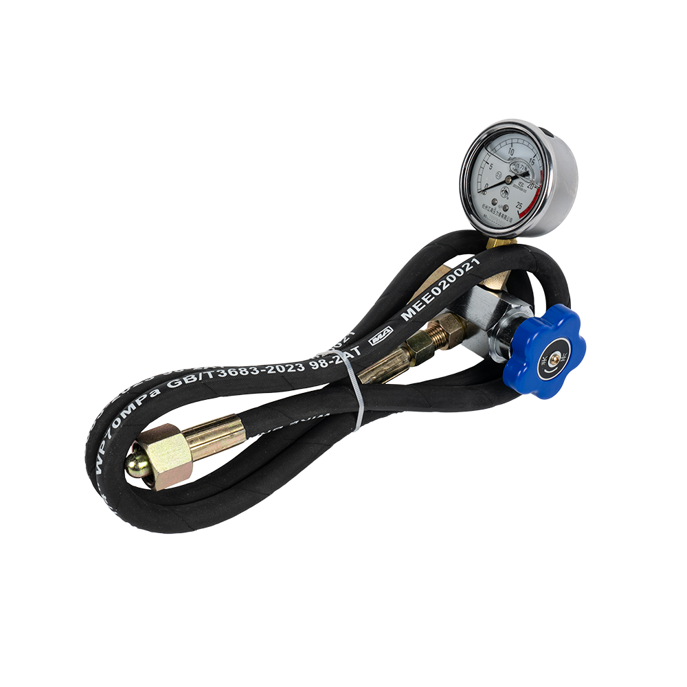 CQJ Accumulator Charging Kit for Nitrogen PrechargeCharges, replenishes and checks accumulator gas pressure with pressure gauge and hose; CQJ-16, CQJ-25 and CQJ-40 cover up to 40 MPa.View Product →
Materials, Temperature and Certification
Offshore nacelles see salt-laden air and permanent humidity, while inland sites see -40 °C and 30 K swings in a single day. Every material choice has to answer for that.
- Diaphragm elastomer. NBR covers -20 to +80 °C with mineral oil. HNBR extends temperature and fatigue life. FKM handles heat and aggressive fluids but stiffens in the cold, and EPDM is the usual answer for water-glycol and many ester-based biodegradable fluids.
- Shell and corrosion protection. Offshore units normally need a stainless shell or a marine coating system on a properly prepared carbon steel surface, and operators should assume the paint gets damaged during installation.
- Fluid compatibility. Many turbine OEMs now specify biodegradable ester fluids, which attack the wrong elastomer and strip the wrong internal coating. Specify for the real fluid, not for mineral oil.
- Certification. Expect PED 2014/68/EU with CE marking for Europe, a Chinese pressure vessel manufacturing licence covering the design pressure and volume, and full material traceability.
Brackets and hoops matter more than they look. A 1 L unit at 250 bar weighs a few kilograms and vibrates continuously, and a bracket that cracks after two years takes the pipework with it.
Common Procurement Mistakes
- Buying on nominal volume. Confirm usable volume at the coldest site temperature, not the datasheet headline.
- Wrong precharge temperature. A workshop setting of 110 bar for a turbine running at -30 °C leaves the pitch system short of pressure exactly when it is needed.
- NBR chosen for a cold site. Standard nitrile can embrittle below -20 °C, and the failure mode is a crack, not a slow leak.
- Undersized ports. If the oil port restricts flow, the feather stroke is slower than the simulation promised.
- No safety block. Without a combined isolation and venting valve, nobody can service or recharge the accumulator safely.
- No spares strategy. Diaphragms and charging kits have lead times, and a 20-year turbine with no spare on site is a planned outage waiting to happen.
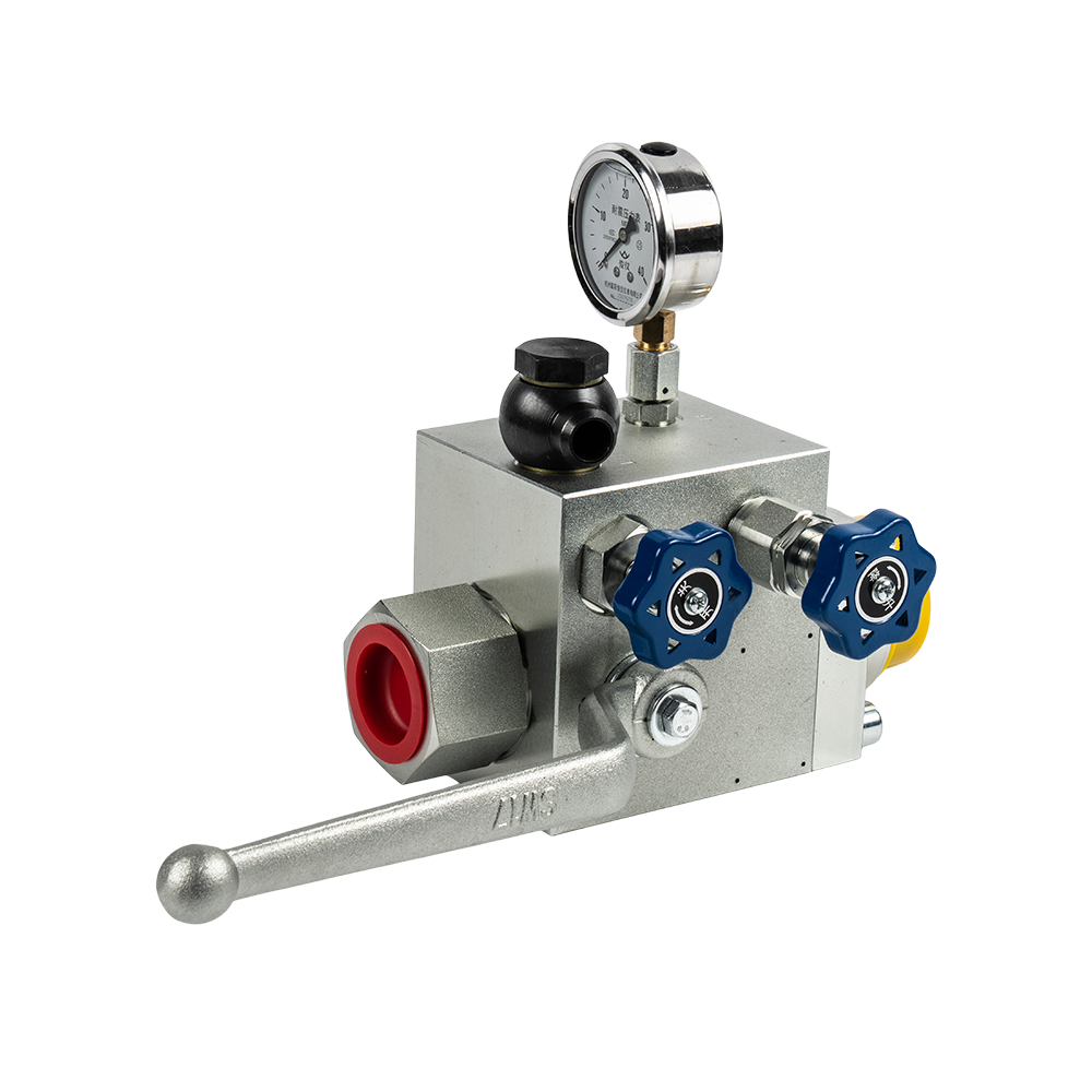 AQF Safety Ball Valve for Bladder Accumulator ProtectionCombines isolation, manual venting and over-pressure relief for bladder accumulators; AQF-L/LS/LW models match 1.6–100 L accumulators.View Product →
A combined safety ball valve answers the fifth point directly: it puts isolation, manual venting and an over-pressure relief path into one block, so a technician can isolate the accumulator before touching a fitting.
What to Look For in the Manufacturer
An accumulator is a commodity part for the supplier and a safety-critical component for the operator, so process control belongs in the specification. Ningbo Fenghua Jiangkou Jingyi Hydraulic Co., Ltd., based in Xikou Town, Ningbo, has manufactured hydraulic and pneumatic components since 2012 and holds a Class A2 pressure vessel manufacturing licence from the Zhejiang market regulator plus CE certification for Europe. Production is controlled from incoming material to finished goods, which is what makes a traceability claim meaningful. The 5,000 square metre workshop and annual capacity of more than 100,000 diaphragm accumulators, 35,000 bladder accumulators and 8,000 piston accumulators answer the question projects ask late in the schedule: can you deliver, and can you deliver again next year? The company sells direct from the factory and exports to overseas markets.
Frequently Asked Questions
What precharge should a diaphragm accumulator have?
Set nitrogen precharge to about 0.8-0.9 times the minimum working pressure, calculated at the coldest expected operating temperature, and never above 0.9 times the relief valve setting.
How often should precharge be checked?
Annually within a normal turbine service interval, and every six months for offshore or cold-climate sites. A drop of more than 10% means top up and investigate.
Can a diaphragm accumulator be mounted horizontally?
Yes. There is no bladder neck that must sit in the oil, so orientation is flexible. Vertical with the gas side up remains the cleanest for venting.
How long does a diaphragm last?
Several years with clean fluid and normal cycling, but it is a wear part. Contamination and over-temperature shorten its life, so filtration matters as much as the accumulator itself.
Getting the Selection Right the First Time
Diaphragm accumulators are a mature answer to energy storage on wind power generators, but they only deliver the safety margin they promise when volume, precharge, elastomer and certification are specified for the real site. If you are sizing a pitch or brake circuit, or replacing units that keep losing precharge, share the working pressure, temperature range and fluid with the factory and ask for the usable volume at -30 °C in writing.
Send your circuit data through the contact page, or start with the wind energy application overview to see how these units are specified across turbine platforms.
PREV: High Pressure Hydraulic Diaphragm Accumulator: Selection, Sizing and Supply GuideNEXT: Diaphragm Accumulator for Tractor Hydraulic Systems: Sizing & Buying Guide
Related Products
-
-
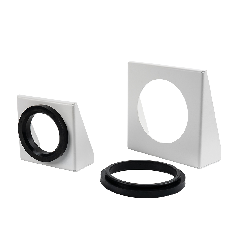
An accumulator bracket is a mechanical device used to fix and support a hydraulic accumulator.
See Details -

An accumulator clamp is a metal fastener specifically designed for securing and supporting hydraulic or pneumatic accumulators. Its primary function is to prevent the accumulator from swaying, deformi...
See Details -
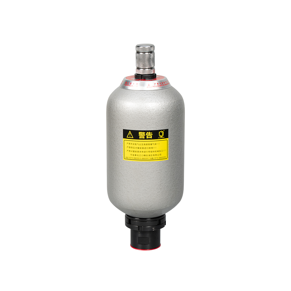
The NXQ Series Bladder Accumulator is a bladder-type accumulator conforming to national standards (JB/T 7036-93) or HG2331. Its core component is the "bladder" or "capsule," hence the name. This serie...
See Details -
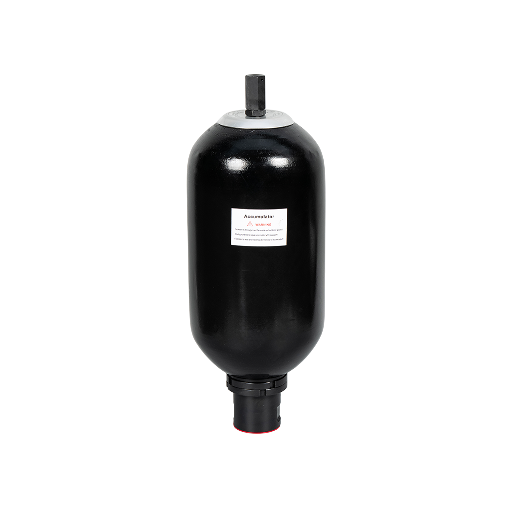
PED-type bladder accumulators refer to bladder accumulators that comply with the EU PED Directive (2014/68/EU). These accumulators typically consist of a steel outer shell and an internal elastic blad...
See Details -
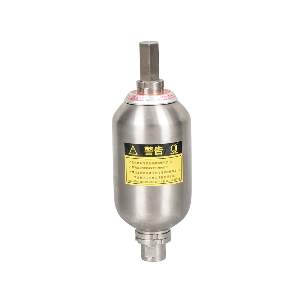
A stainless steel bladder accumulator is an energy storage device used in hydraulic systems. It utilizes the compressibility of a gas (usually nitrogen) to store and release energy, primarily for stab...
See Details
News
-
A hydraulic rock drill striking 2,500 times a minute pushes a pressure pulse into its circuit every 24 milliseconds. The hose flexes, the seals wear, and the pump sees the reflected wave. Diaphragm accumulator...
READ MORE -
A wellhead control panel on an offshore platform often carries less than two litres of usable hydraulic fluid behind each actuator. When the pump stops, that small volume still has to stroke a valve, hold it o...
READ MORE -
A 90 hp utility tractor working a front loader and a loaded grain trailer asks its hydraulic circuit to steer, lift and release the trailer brakes at the same time. When the small diaphragm accumulator support...
READ MORE -
During a typical injection molding cycle, the hydraulic system demands a sudden surge of oil to drive the injection screw forward at high speed. If the pump alone supplies this flow, it must be oversized, wast...
READ MORE -
When a 180-ton mobile crane lowers a fully loaded boom, the inertia can push hydraulic pressure above 400 bar in the luffing cylinder in less than a second. Without a device to absorb that peak, seals fail ear...
READ MORE -
A harvester header that sags a few centimetres every time pump load spikes, or a reel that surges as the engine drops to idle, points to the same root cause: pressure fluctuation that nothing in the circuit is...
READ MORE
contact us

-

-

Mobile: +86-574-88830515
-

Telephone: +86-15968431761
-

No. 12 Xujiabu, Xikou Town, Fenghua District, Ningbo City, Zhejiang Province, P.R.China