
 Español
 中文简体
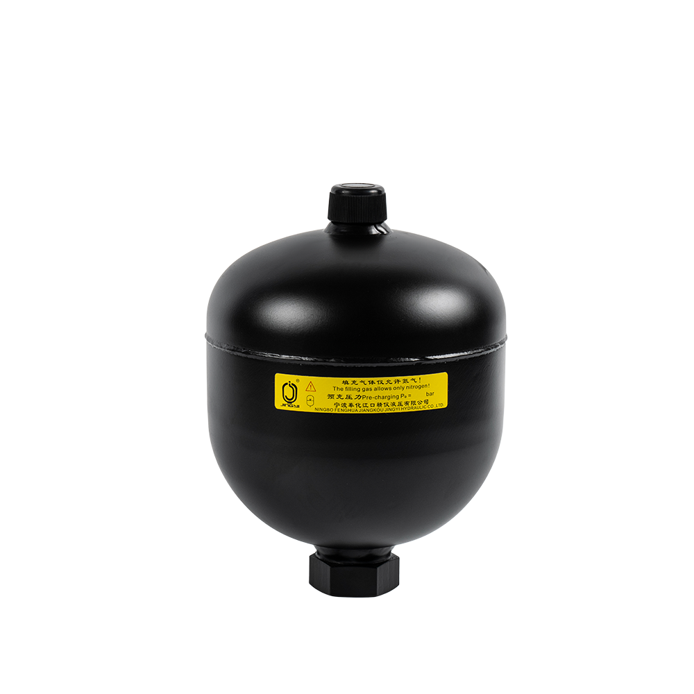
A diaphragm accumulator is a mechanical device that stores and releases energy using Boyle's Law (the compressibility of gases). Its core structure is a diaphragm made of a flexible material (usually ...
See Details
Home / News / Industry News / Threaded Diaphragm Hydraulic Accumulators: Sizing, Threads and Installation
Threaded Diaphragm Hydraulic Accumulators: Sizing, Threads and Installation
Admin 2026-11-06Content
- 1 How a Threaded Diaphragm Accumulator Is Put Together
- 2 Five Duties, Five Different Precharge Settings
- 3 Sizing in Four Steps
- 4 Thread, Seal and Torque: Where Installations Go Wrong
- 5 Installation Details That Decide Service Life
- 6 Precharge Routine and Diaphragm Failure Signs
- 7 Frequently Asked Questions
A 1.5 L threaded diaphragm accumulator screwed straight into a manifold block is one of the tidiest ways to hold clamping pressure on a machine tool. Charge it to 60 bar on a 20 °C bench, ship the same unit to a foundry where the oil side runs at 60 °C, and the nitrogen pressure rises to roughly 68 bar by itself. If nobody re-checks the numbers, the diaphragm now sits too close to the oil port at minimum system pressure, flexes against it, and tears long before its rated cycle life.
Here is the short version: the threaded connection is not the weak point, and it is rarely the cause of a failure. A threaded diaphragm accumulator uses the same pressure-containing shell and the same diaphragm logic as a flanged unit. What changes is how it mounts, how it seals, and how easily a fitter can damage it on site. Get precharge, thread engagement and support right, and these units run for years in spaces where a larger accumulator would never fit.
How a Threaded Diaphragm Accumulator Is Put Together
Inside the shell, a flexible diaphragm — usually NBR, EPDM, FKM or HNBR — is clamped around its full circumference and separates a dry nitrogen chamber from the oil chamber. Nothing rolls and nothing slides: the diaphragm simply flexes, so the gas volume changes through a change of shape rather than a moving seal. That is why the format stays compact, responds quickly to pressure transients, and dominates small precision hydraulic systems.
Nominal volumes generally run from 0.02 L to about 5 L, with working pressures up to roughly 250–350 bar depending on shell design. Beyond a few litres the diaphragm area and shell cost stop making sense, and bladder or piston designs take over.
Threaded port or threaded neck?
- Threaded port: the hydraulic connection is cut into the oil-end shell — G1/2, G3/4, M22×1.5, 7/8-14 UNF or 1/2 NPT — and the unit threads straight into a manifold, a fitting or a safety block. Typical on 0.075–1 L sizes.
- Threaded neck: a longer neck with a mounting nut, so the body hangs in a bracket or hoop clamp while the pipe connects to the port. Typical on 1–4 L sizes where the pipework, not the block, is the mounting point.
- Gas end: a charging valve, usually 5/8-18 UNF or 7/8-14 UNF, with a protective cap. Every precharge check starts here.
Five Duties, Five Different Precharge Settings
A threaded diaphragm accumulator can store energy, damp pulsation, absorb shock, compensate thermal volume and cover leakage. It cannot do all five well at once — each duty wants a different precharge, and a unit sized for pulsation damping is usually too small as an emergency supply. The same trade-off shows up across industrial equipment, from clamp circuits to press holding lines.
- Energy storage and emergency supply: precharge at 0.8–0.9 × minimum working pressure, so stored gas volume is available the moment pump pressure drops.
- Pulsation damping: precharge around 60–80 % of mean working pressure, mounted close to the pump with a short, straight connection. Long hose runs blunt the effect.
- Pressure-peak absorption: precharge near normal working pressure, so the diaphragm starts moving the instant a valve closes.
- Thermal volume compensation: precharge at the low end of the pressure band, with enough gas volume to swallow the expansion of a closed circuit.
- Leakage compensation and holding pressure: slow duty, precharge around 0.9 × minimum pressure, checked against the leakage volume over the hold time.
When two duties matter, size for the larger volume and accept the compromise on precharge — or split the functions across two smaller units.
Sizing in Four Steps
- Define the operating band. Record minimum pressure p1, maximum pressure p2, required usable volume, fluid and the temperature range on both the oil and gas side. Gas temperature lags oil temperature, often by 10–20 °C during start-up.
- Set the precharge. Keep p0 at or below 0.9 × p1 so the diaphragm never presses into the oil port at minimum pressure, and check that the ratio p2 / p0 stays near or under 4:1 for a diaphragm type.
- Correct for temperature. Gas pressure follows absolute temperature: 60 bar charged at 293 K becomes about 68 bar at 333 K. Charge cold and run hot, and the effective precharge has shifted by more than 13 %.
- Calculate the volume, then check the port. For slow, near-isothermal duty, usable volume ≈ V0 × p0 × (1/p1 − 1/p2). Fast cycling behaves closer to adiabatic and gives roughly 10–20 % less usable volume for the same nominal size.
That last check is often skipped. A G1/2 port on a 1 L unit holds pressure perfectly well, but it becomes a restriction when the accumulator has to feed a fast-acting cylinder, and the resulting pressure drop looks exactly like an undersized accumulator.
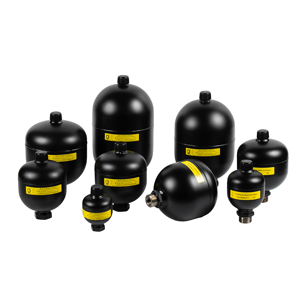 Welded Diaphragm Accumulator for Hydraulic Energy StorageWelded diaphragm accumulator from 0.075 to 3.5 L, with G1/2 or G3/4 connections and pressure ratings to 250 bar; compare port size with flow demand.View Product →
Thread, Seal and Torque: Where Installations Go Wrong
Three faults account for most leaking or loosened threaded joints: a parallel thread forced into a tapered port, too little engagement in an aluminium manifold, and sealant debris migrating into the oil chamber or blocking the gas valve.
| Thread form | How it seals | Typical sizes | Practical notes |
|---|---|---|---|
| G (BSPP), parallel | Flat spotface plus O-ring or bonded washer | G1/2, G3/4, G1 | Keep the spotface flat and unpainted; the thread flanks do not seal |
| Metric, e.g. M22×1.5 | Parallel, O-ring or sealing ring in a counterbore | M18×1.5, M22×1.5 | Check thread length so the O-ring lands fully inside the bore |
| UNF, e.g. 7/8-14 | Parallel with O-ring, fine pitch | 5/8-18 UNF, 7/8-14 UNF | Fine threads are easy to over-torque; use the stated torque figure |
| NPT, e.g. 1/2-14 | Tapered, seals by thread interference plus sealant | 1/2 NPT, 3/4 NPT | Leave one or two threads exposed; apply paste or anaerobic sealant behind the first two threads, never tape |
Engagement rule of thumb: 1 to 1.5 times the nominal diameter in steel-to-steel joints, more when one side is aluminium. Use the maker's torque figure rather than a generic table, and never use the threaded connection to carry the body's weight or to pull a misaligned pipe into place. A spotface that is painted or scratched will leak no matter how tight the joint is.
Installation Details That Decide Service Life
- Support the body with a bracket or hoop clamp, never with the pipe or the port thread. Vibration plus an unsupported 3 L body is a fatigue crack in progress.
- Orientation is free: a clamped diaphragm works in any position, which helps inside tight machine frames. Vertical with the gas valve up simply makes servicing easier.
- Keep heat away. Every 10 °C of gas temperature moves precharge by roughly 3 %, so a shell next to an exhaust run is a precharge error waiting to happen.
- Fit a relief valve or a safety block on the oil side, so the unit can be isolated and depressurised before any thread is loosened.
- Leave access for a charging hose and a gauge. A unit that cannot be checked will not be checked.
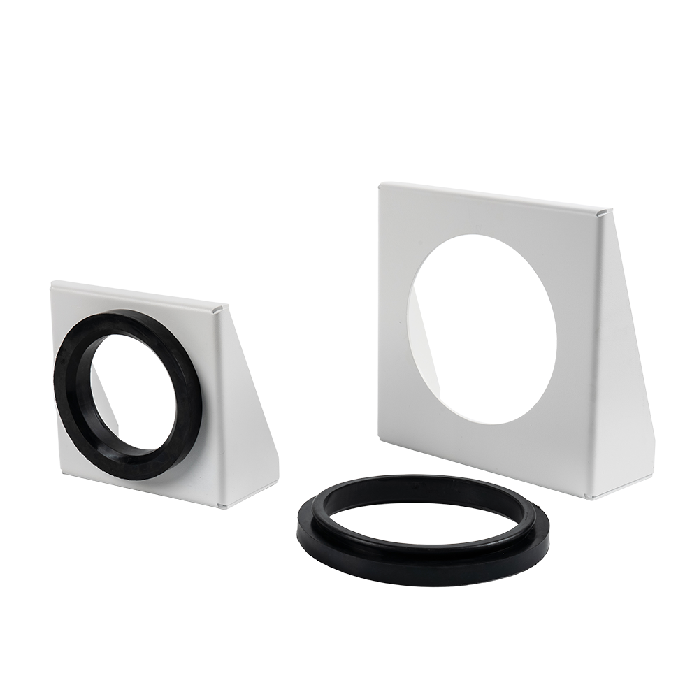 Accumulator Brackets for Φ89 to Φ299 mm BodiesNX-TJ and NX-DQ brackets support accumulator bodies from Φ89 to Φ299 mm, helping secure them against vibration and pressure changes without relying on threaded connections.View Product →
Precharge Routine and Diaphragm Failure Signs
Nitrogen only. Oxygen or compressed air in the gas chamber turns routine maintenance into a hazard, and air carries moisture into the shell.
Check precharge at commissioning, again after the first week, then quarterly on continuously cycling units and annually on standby units. The sequence never changes: isolate, vent the oil side, connect a charging kit, read the gas pressure, top up or release, then re-pressurise.
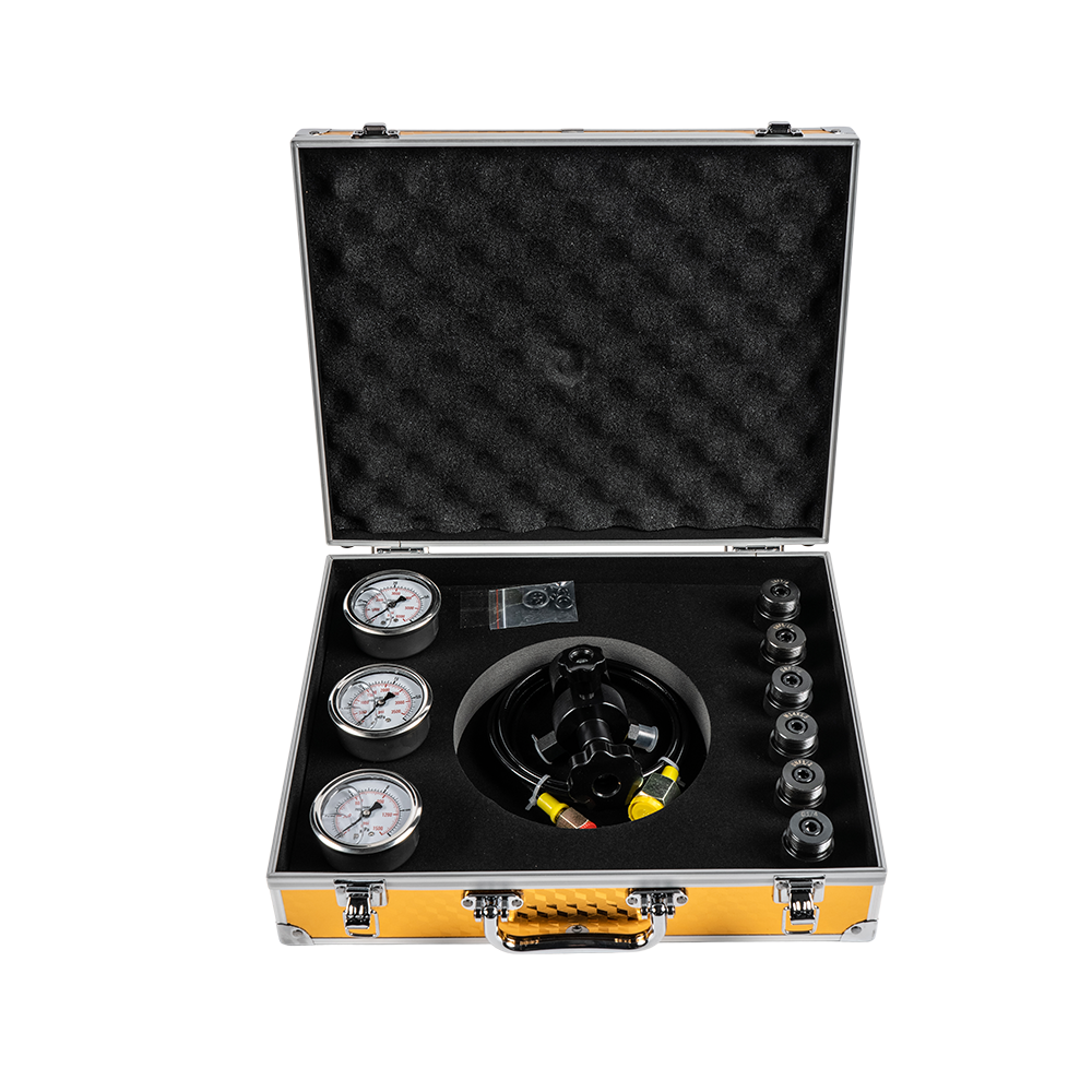 FPU Accumulator Charging and Precharge Check KitsFPU kits charge, replenish, or check accumulator precharge with pressure gauge, high-pressure hose, and adapters for bladder, piston, diaphragm, and bellows types; use nitrogen only.View Product →
Frequently Asked Questions
Can a threaded diaphragm accumulator be mounted horizontally?
Yes. The diaphragm is clamped around its full circumference, so orientation does not affect how it seats — unlike designs that rely on a rolling bladder.
What precharge suits pulsation damping?
Start at 60–80 % of mean working pressure. For a system running between 80 and 120 bar, that is roughly 60–80 bar, provided the unit still has the gas volume to absorb the pulse.
Can the port thread carry the accumulator's weight?
No. Small units often survive it in practice, but anything above about a kilogram should hang from a bracket or hoop clamp with a flexible connection to the pipework.
How often should the precharge be verified?
At commissioning, after the first week, then quarterly or annually by duty. Log the gas temperature with every reading, because a 20 °C shift explains most apparent drift.
Signs the diaphragm has gone: the precharge will not hold, oil appears at the gas valve, gas escapes into the oil and the circuit feels spongy, or a closed circuit loses pressure with no visible leak. Once oil reaches the gas chamber, replace the unit instead of recharging it.
Threaded diaphragm accumulators reward careful arithmetic more than careful shopping. Set precharge against minimum working pressure with a temperature correction, respect the thread and seal combination, support the body, and check the gas side on a schedule — the unit will then deliver exactly what the sizing calculation promised. Where a circuit needs compact pressure storage, pulsation control or thermal compensation in a tight envelope, a diaphragm unit with a threaded connection is usually the simplest answer, and the one that fits the block the machine already has.
PREV: No previous articleNEXT: Diaphragm Accumulator Nitrogen Charged: Precharge Pressure, Purity & Charging Steps
Related Products
News
-
A harvester header that sags a few centimetres every time pump load spikes, or a reel that surges as the engine drops to idle, points to the same root cause: pressure fluctuation that nothing in the circuit is...
READ MORE -
A 315 bar clamping circuit on a die-casting machine has to hold force for about two seconds after the pump stops. A one litre diaphragm accumulator covers that duty with a precharge that stays within a few per...
READ MORE -
A 90 hp utility tractor working a front loader and a loaded grain trailer asks its hydraulic circuit to steer, lift and release the trailer brakes at the same time. When the small diaphragm accumulator support...
READ MORE -
Imagine a machine that needs a short burst of high flow for only five seconds out of every forty-second cycle. If the pump is sized for that peak, the rest of the time it runs oversized, generates unnecessary ...
READ MORE -
Every hydraulic system has a moment when demand exceeds supply. A molding press calls for a sudden surge of fluid; a wind turbine pitch drive needs a short burst of power; a hydraulic rig requires emergency pr...
READ MORE -
A hydraulic rock drill striking 2,500 times a minute pushes a pressure pulse into its circuit every 24 milliseconds. The hose flexes, the seals wear, and the pump sees the reflected wave. Diaphragm accumulator...
READ MORE
contact us

-

-

Mobile: +86-574-88830515
-

Telephone: +86-15968431761
-

No. 12 Xujiabu, Xikou Town, Fenghua District, Ningbo City, Zhejiang Province, P.R.China