
 Español
 中文简体
中文简体A stainless steel bladder accumulator is an energy storage device used in hydraulic systems. It utilizes the compressibility of a gas (usually nitrogen) to store and release energy, primarily for stab...
See Details
Home / News / Industry News / Hydraulic Energy Storage: How Accumulators Store and Release Power in Hydraulic Systems
Hydraulic Energy Storage: How Accumulators Store and Release Power in Hydraulic Systems
Admin 2026-08-14Content
- 1 Why Hydraulic Energy Storage Matters in System Design
- 2 How Accumulators Store and Release Hydraulic Energy
- 3 Bladder, Diaphragm, or Piston: Which Accumulator Type Should You Use?
- 4 Where Hydraulic Energy Storage Delivers the Most Value
- 5 Pre-Charge, Charging Kits, and Maintenance Basics
- 6 Hydraulic Energy Storage vs. Grid-Scale Pumped Storage
- 7 Capacity and Scale: Factory-Level Production Considerations
- 8 Procurement Checklist for Hydraulic Energy Storage Components
- 9 Frequently Asked Questions About Hydraulic Energy Storage
- 10 Making the Right Hydraulic Energy Storage Decision
Imagine a machine that needs a short burst of high flow for only five seconds out of every forty-second cycle. If the pump is sized for that peak, the rest of the time it runs oversized, generates unnecessary heat, and wastes electricity. Hydraulic energy storage solves this by using an accumulator: a component that stores hydraulic energy during low-demand phases and releases it the instant the system asks for force, speed, or pressure. In practice, that changes how the entire pump, motor, and valve train can be designed. This article explains how hydraulic energy storage works, compares the main accumulator technologies, and gives you a practical basis for selecting the right hardware for real production environments.
Why Hydraulic Energy Storage Matters in System Design
The core advantage of an accumulator is that it decouples peak demand from pump capacity. A typical manufacturing press may have an average flow demand of 15 L/min but a peak demand of 60 L/min for clamping or rapid advance. Without energy storage, the pump must supply 60 L/min continuously. The result is higher motor power, larger oil volume, more heat, and a more expensive cooling system. With an accumulator, the pump only needs to handle the average flow, and the accumulator covers the peak.
The practical consequences are measurable: reduced energy consumption, lower oil temperature, smaller reservoir size, and a quieter hydraulic power unit. There is also a reliability benefit. Because the pump spends less time at maximum output, seal wear and component fatigue drop. For machine builders, this often means they can reduce the physical footprint of the power pack without compromising performance.
Hydraulic energy storage is also used for safety-related functions. A spring-loaded or gas-loaded accumulator can hold pressure to keep a clamp closed when the pump is off, or to retract a cylinder in an emergency stop sequence. In these applications, the accumulator is not a convenience component; it is a functional safety element that must be specified, tested, and certified with the same care as the pressure vessel it effectively is.
How Accumulators Store and Release Hydraulic Energy
Nearly all hydraulic accumulators operate by compressing a gas, most commonly nitrogen. When the hydraulic pump pushes oil into the accumulator, the gas volume decreases and pressure rises. When the system needs flow, the compressed gas expands and drives the oil back into the circuit. This process follows the general gas law, where pressure and volume are inversely related. In a fast cycle, the gas behaves in a near-adiabatic way; in a slow cycle, it tends toward isothermal behavior. The difference matters because a rapidly cycling system stores and returns less energy than a system with long dwell times, and the sizing calculation must reflect the actual cycle time.
Pre-charge pressure is the starting point of every energy storage calculation. The normal rule of thumb is to set the pre-charge at roughly 80-90% of the minimum working pressure, or about 90% of the lowest system pressure you want to maintain. Too low a pre-charge leaves most of the gas volume unused; too high a pre-charge prevents the accumulator from storing enough oil. For an engineer, the pre-charge value is the most frequent source of mismatch between a theoretically sized system and a poorly performing one on site. To get accurate recommendations for your circuit and operating pressure, it is worth comparing complete accumulator application fundamentals before buying hardware.
Energy capacity also depends on the pressure range, not just on the gas volume. A 20-liter accumulator operating between 80 and 120 bar stores meaningfully more usable energy than the same accumulator operating between 30 and 40 bar. This is why simple “size equals capacity” thinking fails in hydraulic energy storage. What you need is the effective discharged oil volume between the minimum and maximum working pressures. Suppliers can usually provide curves for their products, and any serious quotation should include these values for your exact pressure window.
Bladder, Diaphragm, or Piston: Which Accumulator Type Should You Use?
Hydraulic accumulator manufacturers generally produce three main geometries, and each one has a distinct operating window. Choosing between them is not a matter of preference; it is a question of flow rate, physical space, required response speed, and maintenance strategy.
| Selection Factor | Bladder Accumulator | Diaphragm Accumulator | Piston Accumulator |
|---|---|---|---|
| Typical capacity range | 0.5 to 50+ liters | 0.05 to 4 liters | 1 to 100+ liters |
| Response dynamics | Fast, smooth response | Fast, compact design | Slower but very stable |
| Pressure stability | Good, sensitive to bladder wear | Good for small volume changes | Excellent repeatability |
| Maintenance need | Bladder replacement every few years | Diaphragm replacement is simple | Seal wear, piston ring care |
| Typical use | General industrial hydraulics | Small precision systems | High pressure / high flow |
For a wide range of industrial circuits, the bladder accumulator design is the most balanced choice. It reacts quickly, tolerates moderate contamination, and is easy to recharge or re-bladder. For smaller machines, compact installations, or circuits with limited mounting space, diaphragm accumulator units offer an effective solution with very few moving parts. For systems that run at very high pressure or need large oil volumes at a steady flow, piston accumulator systems tend to be more robust because the gas and oil are separated by a metal piston rather than an elastomeric element.
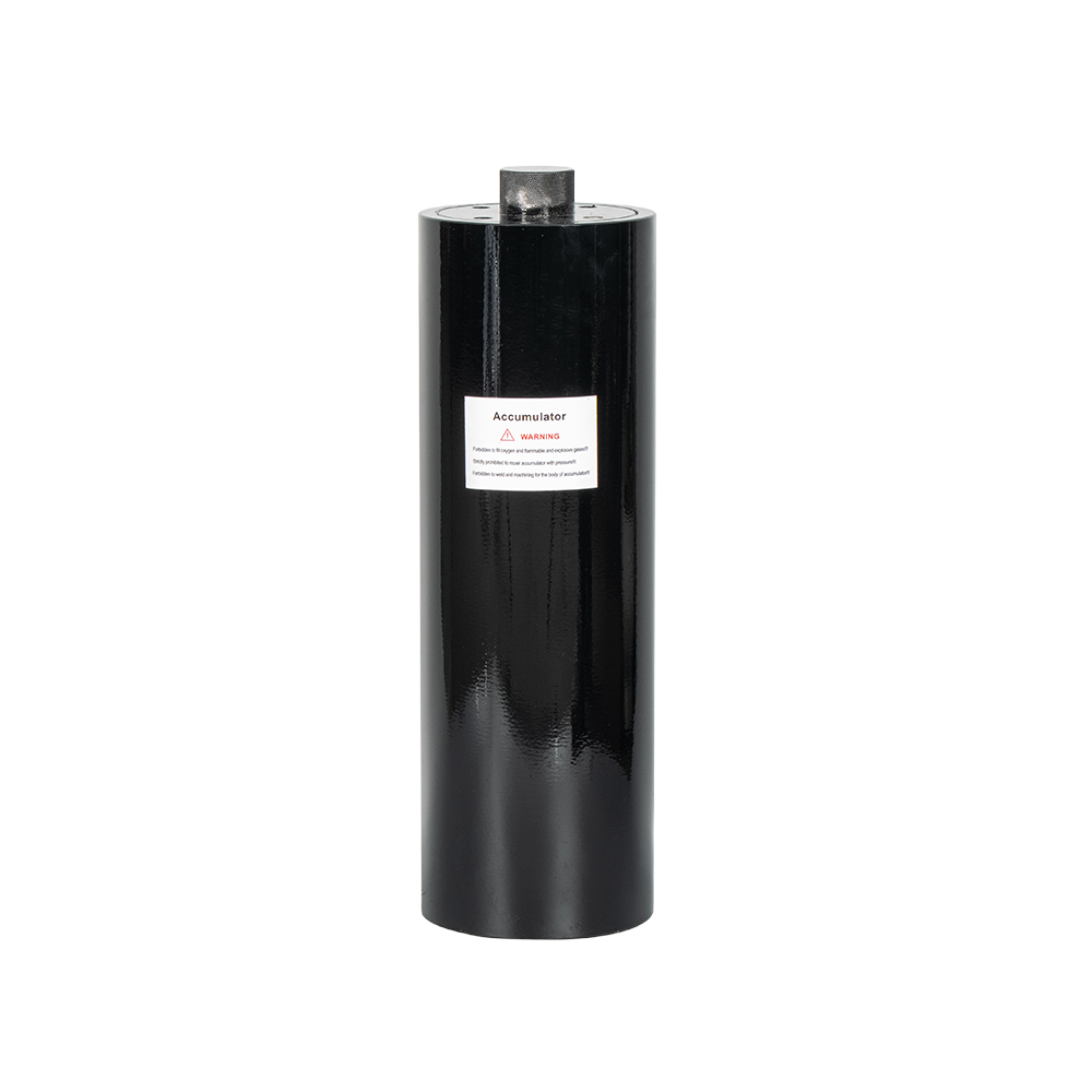 OEM & ODM High Pressure Piston Accumulator Manufacturer, FactoryNingbo Fenghua Jiangkou Jingyi Hydraulic is a China high pressure piston accumulator manufacturer and factory, we offer OEM & ODM piston ...View Product →
 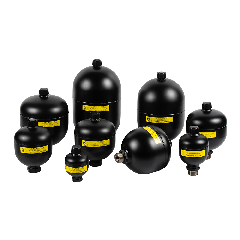 Small Diaphragm Accumulator Manufacturer, Pressure Vessel Accumulator FactoryNingbo Fenghua Jiangkou Jingyi Hydraulic is a China small diaphragm accumulator manufacturer & pressure vessel accumulator factory, we of...View Product →
 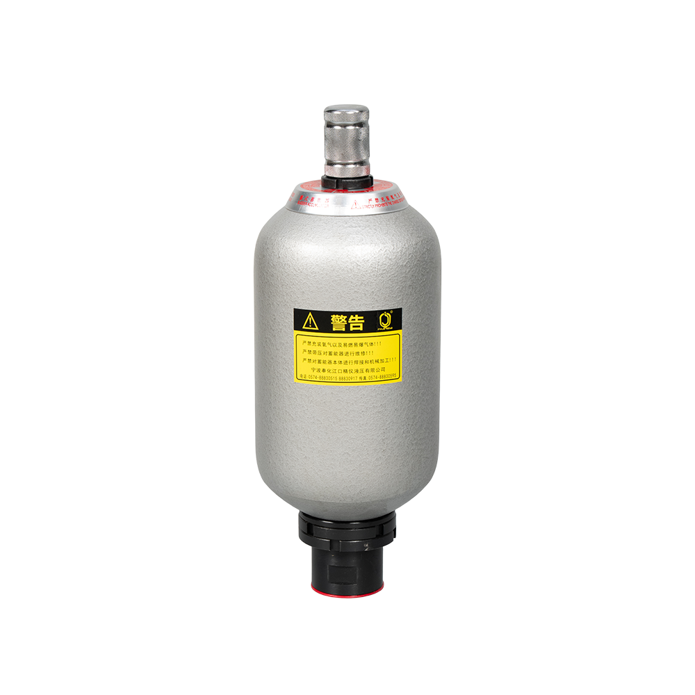 Hydraulic Bladder Accumulator Manufacturer, Standard Bladder Accumulator CompanyAs a China hydraulic bladder accumulator manufacturer and standard bladder accumulator company, Ningbo Fenghua Jiangkou Jingyi Hydraulic ...View Product →
Where Hydraulic Energy Storage Delivers the Most Value
Hydraulic energy storage appears across almost every industry that uses hydraulics, but the value is highest where the duty cycle is uneven. In industrial equipment, accumulators absorb pressure spikes from directional valve switching and provide additional flow when a cylinder accelerates a heavy mass. In wind energy systems, hydraulic accumulators store energy to adjust blade pitch when the control valve demands a very brief but intense flow. In petrochemical plants, gas-loaded accumulators keep critical valves fail-safe in the absence of electric power, and because these applications are safety-related, certified designs and traceable manufacturing matter more than price.
There are four common application patterns where hydraulic energy storage is measured financially. The first is pulse absorption: the accumulator smooths pressure fluctuations caused by pump ripple or sudden valve closure, extending hose life and reducing noise. The second is leakage compensation: a cylinder holding a load for a long period loses small amounts of oil past the seals, and the accumulator replenishes the volume without running the pump continuously. The third is auxiliary power: the accumulator drives a rapid traverse or clamping stroke, enabling faster cycle times. The fourth is emergency operation: stored energy ensures a defined movement—closing a valve, lifting a brake, or retracting a cylinder—if the main power supply fails.
Each pattern has a different sizing input. Pulse absorption is designed around the pressure fluctuation amplitude and the trapped oil volume. Leakage compensation is designed around the leakage rate multiplied by dwell time. Auxiliary power is designed around the required oil volume per stroke, while emergency operation usually follows a required response time under a fixed pressure drop. If you apply the correct boundary condition, the accumulator size becomes a calculation result; otherwise it remains a guess that can only be corrected after the machine is already running.
Pre-Charge, Charging Kits, and Maintenance Basics
Hydraulic energy storage depends far more on the gas side than many maintenance teams realize. A nitrogen pre-charge that has dropped by only 10-15% can reduce effective oil capacity by a large margin. Regular pre-charge checks are essential, especially in plants with high ambient temperature or frequent pressure cycling. Checking the pre-charge requires a charging device that connects through the accumulator gas valve, and the procedure usually involves shutting down the system, blocking the pressure, and reading the gas-side pressure through a gauge. A proper accumulator charging kit selection and usage reference will clarify which connection type, hose length, and gauge range are appropriate for your valve configuration.
Two practical maintenance rules apply across all accumulator types. First, never work on an accumulator when it still holds hydraulic pressure. Always depressurize the oil side and release the gas side to atmospheric level before disassembly. Second, replace an elastomeric bladder or diaphragm if there are signs of permanent deformation, cracks, or a sticky surface. In extreme cases, a ruptured bladder can push rubber debris into the hydraulic system and damage valves and pumps downstream. If the application involves food, pharmaceutical, or offshore environments, also check the elastomer material compatibility with the fluid and cleaning agents.
Hydraulic Energy Storage vs. Grid-Scale Pumped Storage
Searching “hydraulic energy storage” sometimes returns articles about pumped hydroelectric storage, where water is pumped uphill and released through turbines to generate electricity. Both technologies share the same underlying logic—store energy in a fluid and release it later—but they operate on completely different scales. Pumped storage plants hold hundreds of megawatt-hours and respond over minutes, while a hydraulic accumulator in a production line holds a few kilojoules and responds in fractions of a second. Understanding the distinction prevents confusion when quoting test standards or energy figures.
For an industrial buyer, the relevant scale is the one that sits next to a pump, a valve block, or a cylinder. This is not “hydraulic energy storage” in the sense of a national electricity grid; it is compact, machine-local energy storage. The performance metric to use is the effective discharged oil volume at working pressure, not the gas volume of the bladder or the nominal accumulator size. When comparing suppliers, ask for the discharge curve, proof pressure, operating temperature range, and whether the unit carries a pressure vessel classification. Certifications such as the Chinese A2 pressure vessel license and the European CE marking are practical guarantees of design validation for high-pressure service.
Capacity and Scale: Factory-Level Production Considerations
For OEMs and purchasing teams, long-term supply reliability is as important as the accumulator specification itself. Hydraulic energy storage components are not high-volume consumables; they are engineered pressure parts with defined inspection and testing requirements. When evaluating a manufacturer, look beyond the catalog data and examine the facility capacity and process controls. A supplier that can produce large quantities with traceable batch testing is more likely to deliver consistent quality over years of supply.
Illustrative annual production capacity of a mid-size accumulator manufacturer
Bladder
Diaphragm
Piston
Bars are scaled for readability; true annual output figures are stated on each bar.
One example of this balance is the production setup at Ningbo Fenghua Jiangkou Jingyi Hydraulic, a manufacturer operating from a 5,000 m² facility and producing more than 150,000 accumulators per year across bladder, diaphragm, and piston lines. For an OEM, that scale means short lead times and consistent parts supply. For a plant engineer, it also means replacement bladders and charging accessories come from the same source, reducing compatibility risks. Factory-direct supply is another factor that matters because it removes the cost buffer of an intermediary, but the decision should never be based on price alone. Insist on the same pressure vessel documentation and test reports in every delivery, including the ones that arrive years into the partnership.
Procurement Checklist for Hydraulic Energy Storage Components
- Define the operating pressure window and the effective discharge volume required per cycle.
- Choose the accumulator type according to response speed, space constraints, and maintenance preference.
- Verify local pressure vessel regulations and confirm that the manufacturer holds the relevant certification.
- Check fluid compatibility for the bladder, diaphragm, and seal materials.
- Confirm the pre-charge procedure and the availability of the matching charging kit with gauges and connectors.
- Request batch test certificates and confirm that serial numbers allow full traceability.
- Evaluate long-term supply: catalog depth, spare parts availability, and production capacity as delivery commitments grow.
Frequently Asked Questions About Hydraulic Energy Storage
What pressure range is suitable for an accumulator pre-charge?
For gas-loaded accumulators, the pre-charge pressure is normally set at 80-90% of the minimum working pressure. If your minimum working pressure is 100 bar, a pre-charge of 80 to 90 bar is a reasonable starting point. In practice, the exact value also depends on the accumulator design and the manufacturer’s recommendations.
How much energy can a hydraulic accumulator store?
This depends on the gas volume and the pressure range. A small 4-liter diaphragm accumulator with a 100-bar working pressure may store only a few kilojoules of usable energy, which is enough for a simple clamping or cushioning function. A large 100-liter piston accumulator in a high-pressure system can store far more energy and deliver a meaningful fraction of a pump’s power for several seconds, but it is still a low-energy-density device compared with a battery.
How often should an accumulator be inspected?
A common practical interval is every six to twelve months, depending on the operating cycle and ambient temperature. Systems with frequent pressure cycling or temperatures above 60°C need more frequent pre-charge checks. Visual inspection of the external shell can usually be done monthly, especially in mobile or offshore installations where vibration and corrosion are present.
Can a bladder accumulator be repaired instead of replaced?
Yes. The bladder is a replaceable elastomeric component. If the shell and valve fittings are undamaged, fitting a new bladder of the correct material and size restores the accumulator to service. This is why sourcing spare bladders from the same manufacturer as the accumulator body is important for dimension accuracy and material consistency.
Making the Right Hydraulic Energy Storage Decision
Hydraulic energy storage is not a single product category; it is a design philosophy that lets machines run with the right pump size, the right motor power, and a more efficient energy flow. The practical result is a competitive advantage in both operating cost and reliability. Start by defining the pressure window and the real oil demand of each cycle, then compare accumulator type, certification, and supply stability. For teams with high-volume requirements or complex installations, a manufacturing partner that offers full support—from product selection to charging tools and replacement parts—will reduce project risk. Begin the conversation early and bring your actual cycle data, because the quality of the solution depends much more on the input parameters than on the accumulator catalog.
PREV: Hydraulic Energy Storage Explained: How Accumulators Store and Release Fluid PowerNEXT: What Is an Accumulator Nitrogen Charging Kit?
Related Products
-
-
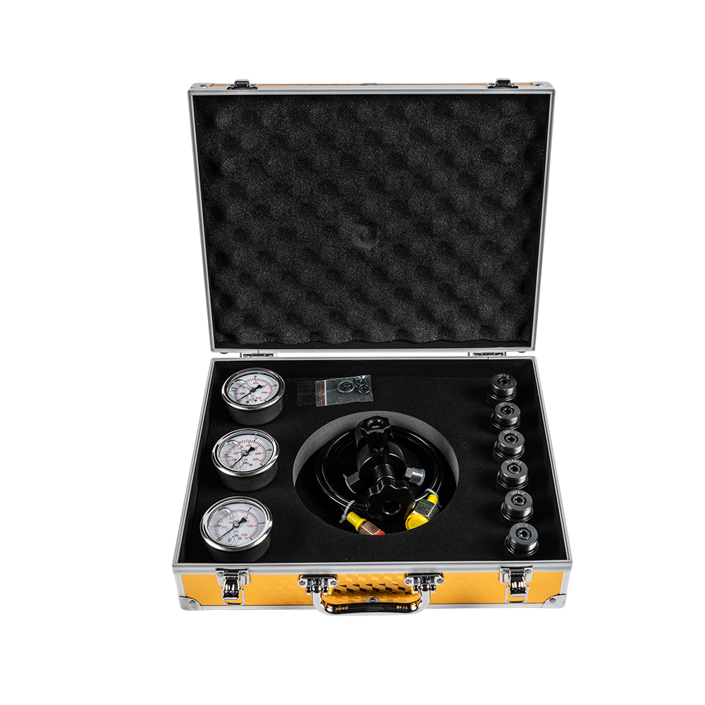
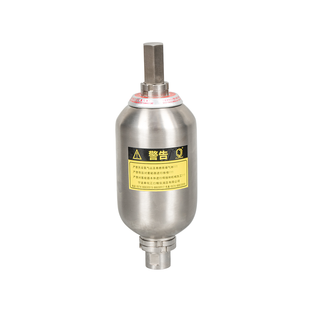
An FPU Charging Kit is a multi-functional tool kit specifically designed for the maintenance of hydraulic accumulators. Its core function is to charge, replenish, or adjust the pre-charge pressure of ...
See Details -
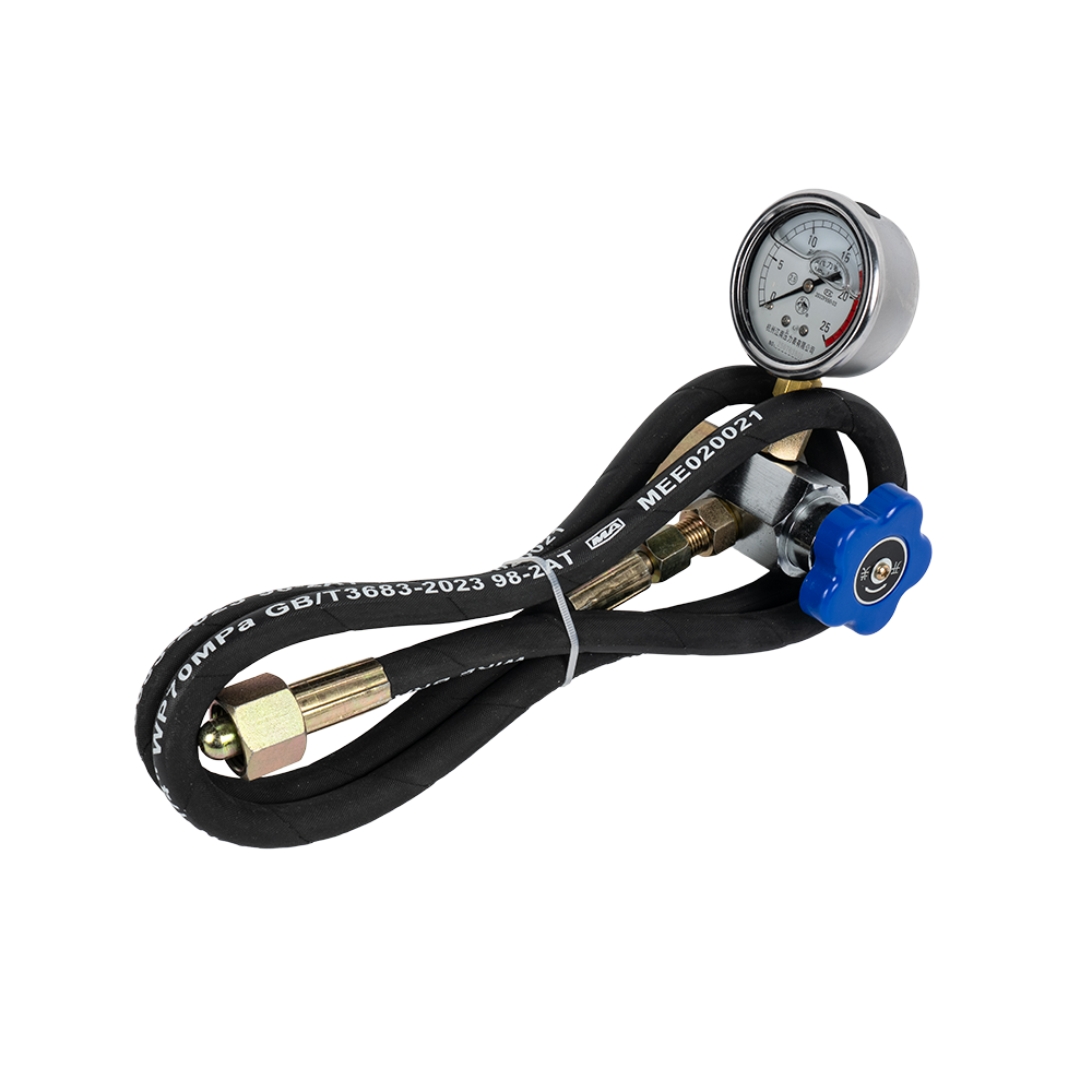
The CQJ charging kit is a specialized tool for charging, replenishing, correcting, and checking the charging pressure of accumulators in hydraulic systems.
See Details -
The 5/8 UNF Charging kit is a high-pressure tool specifically designed for charging or filling hydraulic systems (such as accumulators) with nitrogen or gas. "UNF" refers to the thread specification o...
See Details
News
-
Every hydraulic system has a moment when demand exceeds supply. A molding press calls for a sudden surge of fluid; a wind turbine pitch drive needs a short burst of power; a hydraulic rig requires emergency pr...
READ MORE -
Diaphragm accumulators adopt a diaphragm separation structure. They are compact in size, leak-proof, and highly responsive, making them suitable for pressure stabilization and small flow compensation in micro h...
READ MORE -
Piston accumulators separate gas and fluid with metal pistons. They feature strong pressure resistance and a wide range of volume options, enabling high-pressure energy storage and long-term pressure maintenanc...
READ MORE -
How to Choose the Right Hydraulic Valve: The Direct Answer Choosing the right hydraulic valve for an application comes down to five core parameters: valve function (directional, pressure, or flow control), sys...
READ MORE -
Your hydraulic system is pitting. Salt water, chemical washdown, or process fluid is attacking the accumulator shell. Standard carbon steel or even 304 stainless steel cannot withstand the chloride levels in m...
READ MORE -
Bladder accumulators use rubber bladders to separate gas and fluid. They feature fast response and good sealing performance, effectively absorbing pressure pulsations and compensating flow. Suitable for medium ...
READ MORE
contact us

-

-

Mobile: +86-574-88830515
-

Telephone: +86-15968431761
-

No. 12 Xujiabu, Xikou Town, Fenghua District, Ningbo City, Zhejiang Province, P.R.China